| B |  |
| GO TO DTC CHART (P0A1F-123) (Click here) |
DTC P0AC1-123 Hybrid Battery Pack Current Sensor Circuit Low |
DTC P0AC2-123 Hybrid Battery Pack Current Sensor Circuit High |
| DTC No. | DTC Detection Condition | Trouble Area |
| P0AC1-123 P0AC2-123 | When the battery current sensor is abnormal (1 trip detection) |
|
| Related DTCs | P0AC1-123/P0AC2-123 |
| Required sensors/components | Battery current sensor |
| Frequency of operation | Continuous |
| Duration | TOYOTA's intellectual property |
| MIL operation | Immediately |
| Sequence of operation | None |
| The monitor will run whenever the DTCs listed are not present | TOYOTA's intellectual property |
| TOYOTA's intellectual property | - |
| Battery smart unit | P0AC1-123 / P0AC2-123 is not detected |
| 1.CHECK DTC OUTPUT (DTC P0A1F-123 IS OUTPUT) |
Connect the Techstream to the DLC3.
Turn the power switch on (IG).
Select the following menu items: Powertrain / Hybrid Control / Trouble Codes.
Read output DTCs (Click here).
| Result | Proceed to |
| P0A1F-123 is not output. | A |
| P0A1F-123 is also output. | B |
|
| ||||
| A | |
 |
| 2.CHECK BATTERY PACK WIRE (BATTERY SMART UNIT - BATTRY CURRENT SENSOR) |
Remove the service plug grip (Click here).
Remove the battery cover (Click here).
Disconnect the z18 connector from the battery smart unit (Click here).
Disconnect the z19 HV relay assembly (battery current sensor) connector (Click here).
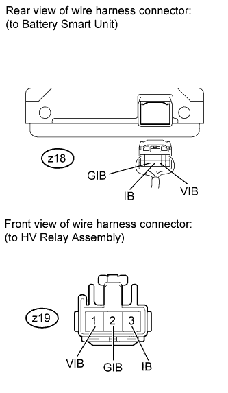 |
Measure the resistance according to the value(s) in the table below.
| Tester Connection | Switch Condition | Specified Condition |
| z18-11 (IB) - z19-3 (IB) | Power switch off | Below 1 Ω |
| z18-12 (GIB) - z19-2 (GIB) | Power switch off | Below 1 Ω |
| z18-10 (VIB) - z19-1 (VIB) | Power switch off | Below 1 Ω |
| Tester Connection | Switch Condition | Specified Condition |
| z18-11 (IB) or z19-3 (IB) - Body ground and other terminals | Power switch off | 10 kΩ or higher |
| z18-12 (GIB) or z19-2 (GIB) - Body ground and other terminals | Power switch off | 10 kΩ or higher |
| z18-10 (VIB) or z19-1 (VIB) - Body ground and other terminals | Power switch off | 10 kΩ or higher |
|
| ||||
| OK | |
|
| 3.INSPECT BATTERY CURRENT SENSOR |
Connect the z19 HV relay assembly (battery current sensor) connector.
Connect the z18 connector to the battery smart unit.
Turn the power switch on (IG).
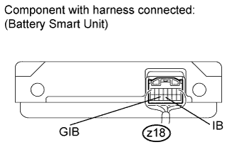 |
Measure the voltage according to the value(s) in the table below.
| Tester Connection | Switch Condition | Specified Condition |
| z18-11 (IB) - z18-12 (GIB) | Power switch on (IG) | 2.46 to 2.54 V |
|
| ||||
| OK | ||
 | ||
| ||