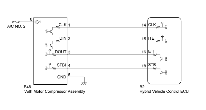
DTC P3108-535 A/C Amplifier Communication Circuit Malfunction |
DTC P3108-536 A/C Amplifier Communication Circuit Malfunction |
DTC P3108-538 A/C Amplifier Communication Circuit Malfunction |
| DTC No. | INF Code | DTC Detection Condition | Trouble Area |
| P3108 | 535 | Serial communication error |
|
| 536 | A/C inverter malfunction | ||
| 538 | Open in the STB signal circuit |
| 1.CHECK DTC OUTPUT (HV) |
Connect the Techstream to the DLC3.
Turn the power switch on (IG).
Select the following menu items: Powertrain / Hybrid Control / Trouble Codes.
Check if DTCs are output.
| Result | Proceed to |
| P3108-535, P3108-536, or P3108-538 only is output. | A |
| Any of the following DTCs are also output. | B |
| DTC No. | Relevant Diagnosis |
| P0ADC-226 | Hybrid Battery Positive Contactor Control Circuit High |
| P0AE0-228 | Hybrid Battery Negative Contactor Control Circuit High |
|
| ||||
| A | |
 |
| 2.CHECK CONNECTOR CONNECTION CONDITION (HYBRID VEHICLE CONTROL ECU CONNECTOR) |
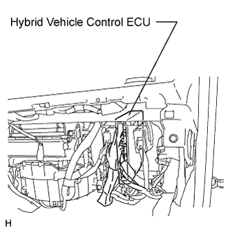 |
Check the connections of the hybrid vehicle control ECU connectors.
|
| ||||
| OK | |
|
| 3.CHECK CONNECTOR CONNECTION CONDITION (WITH MOTOR COMPRESSOR ASSEMBLY CONNECTOR) |
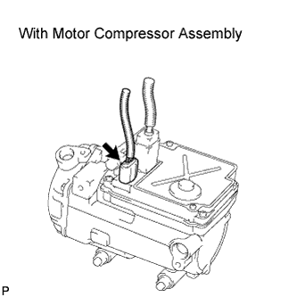 |
Check the connection of the low voltage connector of the with motor compressor assembly.
|
| ||||
| OK | |
|
| 4.CHECK HARNESS AND CONNECTOR (WITH MOTOR COMPRESSOR ASSEMBLY) |
Turn the power switch off.
Disconnect the with motor compressor assembly connector.
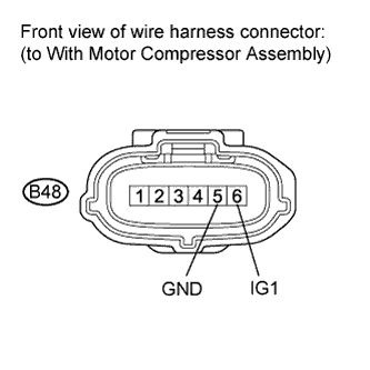 |
Measure the resistance according to the value(s) in the table below.
| Tester Connection | Switch Condition | Specified Condition |
| B48-5 (GND) - Body ground | Power switch off | Below 1 Ω |
Turn the power switch on (IG).
Measure the voltage according to the value(s) in the table below.
| Tester Connection | Switch Condition | Specified Condition |
| B48-6 (IG1) - B48-5 (GND) | Power switch on (IG) | 11 to 14 V |
|
| ||||
| OK | |
|
| 5.CHECK DTC OUTPUT (HV) |
Turn the power switch off.
Connect the with motor compressor assembly connector.
Connect the Techstream to the DLC3.
Turn the power switch on (IG).
Select the following menu items: Powertrain / Hybrid Control / Trouble Codes.
Check if DTCs are output.
| Result | Proceed to |
| P3108-535 is output. | A |
| P3108-535 is not output and P3108-538 is output. | B |
| P3108-538 is not output and P3108-536 is output. | A |
|
| ||||
| A | |
|
| 6.CHECK HARNESS AND CONNECTOR (HYBRID VEHICLE CONTROL ECU - WITH MOTOR COMPRESSOR ASSEMBLY) |
Turn the power switch off.
Disconnect connector B2 from the hybrid vehicle control ECU.
Turn the power switch on (IG).
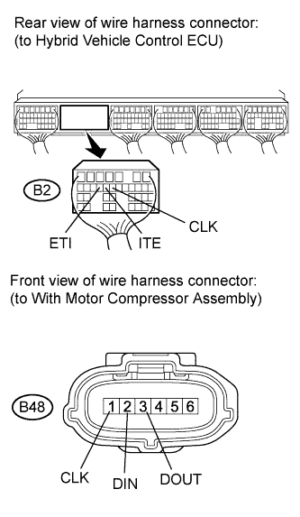 |
Measure the voltage according to the value(s) in the table below.
| Tester Connection | Switch Condition | Specified Condition |
| B2-14 (CLK) - Body ground | Power switch on (IG) | Below 1 V |
| B2-15 (ITE) - Body ground | Power switch on (IG) | Below 1 V |
| B2-16 (ETI) - Body ground | Power switch on (IG) | Below 1 V |
Turn the power switch off.
Measure the resistance according to the value(s) in the table below.
| Tester Connection | Switch Condition | Specified Condition |
| B2-14 (CLK) - B48-1 (CLK) | Power switch off | Below 1 Ω |
| B2-15 (ITE) - B48-2 (DIN) | Power switch off | Below 1 Ω |
| B2-16 (ETI) - B48-3 (DOUT) | Power switch off | Below 1 Ω |
| Tester Connection | Switch Condition | Specified Condition |
| B2-14 (CLK) or B48-1 (CLK) - Body ground and other terminals | Power switch off | 10 kΩ or higher |
| B2-15 (ITE) or B48-2 (DIN) - Body ground and other terminals | Power switch off | 10 kΩ or higher |
| B2-16 (ETI) or B48-3 (DOUT) - Body ground and other terminals | Power switch off | 10 kΩ or higher |
|
| ||||
| OK | |
|
| 7.CHECK HYBRID VEHICLE CONTROL ECU |
Turn the power switch off.
Connect the hybrid vehicle control ECU connector.
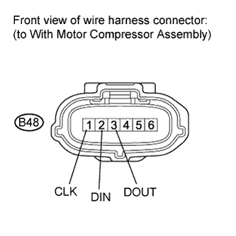 |
Measure the resistance according to the value(s) in the table below.
| Tester Connection | Switch Condition | Specified Condition |
| B48-3 (DOUT) - Body ground | Power switch off | 10 kΩ or higher |
Turn the power switch on (IG).
Measure the voltage according to the value(s) in the table below.
| Tester Connection | Switch Condition | Specified Condition |
| B48-1 (CLK) - Body ground | Power switch on (IG) | 11 to 14 V |
| B48-2 (DIN) - Body ground | Power switch on (IG) | 11 to 14 V |
| B48-3 (DOUT) - Body ground | Power switch on (IG) | Below 1 V |
|
| ||||
| OK | |
|
| 8.CHECK WITH MOTOR COMPRESSOR ASSEMBLY |
Turn the power switch off.
Connect the with motor compressor assembly connector.
Disconnect connector B2 from the hybrid vehicle control ECU.
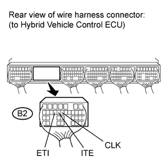 |
Measure the resistance according to the value(s) in the table below.
| Tester Connection | Switch Condition | Specified Condition |
| B2-14 (CLK) - Body ground | Power switch off | 10 kΩ or higher |
| B2-15 (ITE) - Body ground | Power switch off | 10 kΩ or higher |
Turn the power switch on (IG).
Measure the voltage according to the value(s) in the table below.
| Tester Connection | Switch Condition | Specified Condition |
| B2-16 (ETI) - Body ground | Power switch on (IG) | 11 to 14 V |
| B2-14 (CLK) - Body ground | Power switch on (IG) | Below 1 V |
| B2-15 (ITE) - Body ground | Power switch on (IG) | Below 1 V |
|
| ||||
| OK | ||
 | ||
| ||
| 9.CHECK HARNESS AND CONNECTOR (HYBRID VEHICLE CONTROL ECU - WITH MOTOR COMPRESSOR ASSEMBLY) |
Turn the power switch off.
Disconnect connector B2 from the hybrid vehicle control ECU.
Turn the power switch on (IG).
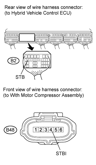 |
Measure the voltage according to the value(s) in the table below.
| Tester Connection | Switch Condition | Specified Condition |
| B2-18 (STB) - Body ground | Power switch on (IG) | Below 1 V |
Turn the power switch off.
Measure the resistance according to the value(s) in the table below.
| Tester Connection | Switch Condition | Specified Condition |
| B2-18 (STB) - B48-4 (STBI) | Power switch off | Below 1 Ω |
| Tester Connection | Switch Condition | Specified Condition |
| B2-18 (STB) or B48-4 (STBI) - Body ground and other terminals | Power switch off | 10 kΩ or higher |
|
| ||||
| OK | |
|
| 10.CHECK HYBRID VEHICLE CONTROL ECU |
Turn the power switch off.
Connect the hybrid vehicle control ECU connector.
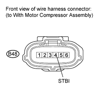 |
Measure the resistance according to the value(s) in the table below.
| Tester Connection | Switch Condition | Specified Condition |
| B48-4 (STBI) - Body ground | Power switch off | 10 kΩ or higher |
Turn the power switch on (IG).
Measure the voltage according to the value(s) in the table below.
| Tester Connection | Switch Condition | Specified Condition |
| B48-4 (STBI) - Body ground | Power switch on (IG) | Below 1 V |
|
| ||||
| OK | |
|
| 11.CHECK WITH MOTOR COMPRESSOR ASSEMBLY |
Turn the power switch off.
Connect the with motor compressor assembly connector.
Disconnect connector B2 from the hybrid vehicle control ECU.
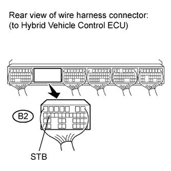 |
Measure the resistance according to the value(s) in the table below.
| Tester Connection | Switch Condition | Specified Condition |
| B2-18 (STB) - Body ground | Power switch off | 10 kΩ or higher |
Turn the power switch on (IG).
Measure the voltage according to the value(s) in the table below.
| Tester Connection | Switch Condition | Specified Condition |
| B2-18 (STB) - Body ground | Power switch on (IG) | 11 to 14 V |
|
| ||||
| OK | ||
| ||
| ||

