2GR-FE ENGINE MECHANICAL CYLINDER HEAD GASKET INSTALLATION
CAUTION / NOTICE / HINT
- HINT:
-
Perform "Inspection After Repair" after replacing the cylinder head sub-assembly RH or cylinder head sub-assembly LH.
-
Click hereEngine / Hybrid System>2GR-FE ENGINE CONTROL>SFI SYSTEM>INITIALIZATION
PROCEDURE

 11115
1.INSTALL CYLINDER HEAD GASKET RH
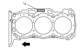
| *a | Lot No. |

|
Engine Front |
Place a new cylinder head gasket RH on the cylinder block sub-assembly with the lot No. stamp facing upward.
- NOTICE:
-
Be careful of the installation direction.
11101
2.INSTALL CYLINDER HEAD SUB-ASSEMBLY RH
Place the cylinder head sub-assembly RH on the cylinder block sub-assembly.
- NOTICE:
- ·
Be careful not to allow oil to adhere to the bottom of the cylinder head sub-assembly RH.
·Gently lower the cylinder head sub-assembly RH in order not to damage the gasket with the bottom of the cylinder head.
- HINT:
-
The cylinder head set bolts are tightened in 3 progressive steps.
Apply a light coat of engine oil to the threads and under the heads of the cylinder head set bolts.
Step 1:
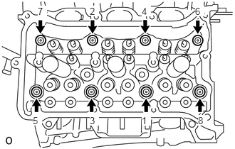
Using a 10 mm bi-hexagon wrench, install and uniformly tighten the 8 cylinder head set bolts with the plate washers in several steps in the order shown in the illustration.
- Torque:
- 36 N*m (367 kgf*cm, 27 ft.*lbf)
Step 2:
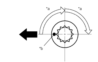
| *a | Turn 90° |
| *b | Paint Mark |
|
|
Engine Front |
Mark each cylinder head set bolt head with paint as shown in the illustration.
Tighten the cylinder head set bolts by 90° in the order shown in step 1.
Step 3:
Tighten the cylinder head set bolts by an additional 90° in the order shown in step 1.
Check that the paint marks are now facing rearward.
- HINT:
-
Perform "Inspection After Repair" after replacing the cylinder head sub-assembly RH.
-
Click hereEngine / Hybrid System>2GR-FE ENGINE CONTROL>SFI SYSTEM>INITIALIZATION
11116
3.INSTALL CYLINDER HEAD GASKET LH
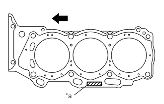
| *a | Lot No. |
|
|
Engine Front |
Place a new cylinder head gasket LH on the cylinder block sub-assembly with the lot No. stamp facing upward.
- NOTICE:
-
Be careful of the installation direction.
11102
4.INSTALL CYLINDER HEAD SUB-ASSEMBLY LH
Place the cylinder head sub-assembly LH on the cylinder block sub-assembly.
- NOTICE:
- ·
Be careful not to allow oil to adhere to the bottom of the cylinder head sub-assembly LH.
·Gently lower the cylinder head sub-assembly LH in order not to damage the gasket with the bottom of the cylinder head.
- HINT:
-
The cylinder head set bolts are tightened in 3 progressive steps.
Apply a light coat of engine oil to the threads and under the heads of the cylinder head set bolts.
Step 1:
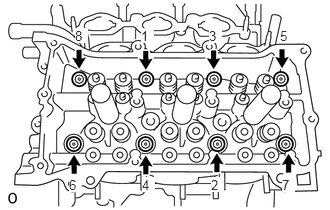
Using a 10 mm bi-hexagon wrench, install and uniformly tighten the 8 cylinder head set bolts with the plate washers in several steps in the order shown in the illustration.
- Torque:
- 36 N*m (367 kgf*cm, 27 ft.*lbf)
Step 2:
| *a | Turn 90° |
| *b | Paint Mark |
|
|
Engine Front |
Mark each cylinder head set bolt head with paint as shown in the illustration.
Tighten the cylinder head set bolts by 90° in the order shown in step 1.
Step 3:
Tighten the cylinder head set bolts by an additional 90° in the order shown in step 1.
Check that the paint marks are now facing rearward.
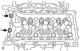
Tighten the 2 bolts in the order shown in the illustration.
- Torque:
- 30 N*m (306 kgf*cm, 22 ft.*lbf)
- HINT:
-
Perform "Inspection After Repair" after replacing the cylinder head sub-assembly LH.
-
Click hereEngine / Hybrid System>2GR-FE ENGINE CONTROL>SFI SYSTEM>INITIALIZATION
16331
5.INSTALL WATER OUTLET
13716
6.INSTALL VALVE STEM CAP
Install the 24 valve stem caps.
13750
7.INSTALL VALVE LASH ADJUSTER ASSEMBLY
Inspect the valve lash adjuster assembly.
Click hereEngine / Hybrid System>2GR-FE ENGINE MECHANICAL>ENGINE UNIT>INSPECTION
Install the 24 valve lash adjuster assemblies to the cylinder head sub-assembly.
13801
8.INSTALL NO. 1 VALVE ROCKER ARM SUB-ASSEMBLY
- HINT:
-
Type A and Type B can be distinguished by the shape of the compression spring.
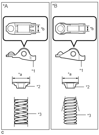
| *A | Type A |
| *B | Type B |
| *1 | No. 1 Valve Rocker Arm Sub-assembly |
| *2 | Valve Spring Retainer |
| *3 | Inner Compression Spring |
| *a | Valve Spring Retainer Diameter |
| *b | No. 1 Valve Rocker Arm Sub-assembly Roller Width |
| Type | No. 1 Valve Rocker Arm Sub-assembly Roller Width | Valve Spring Retainer Diameter | Inner Compression Spring Shape |
|---|---|---|---|
| A | 10.7 mm (0.421 in.) | 23.4 mm (0.921 in.) | Straight |
| B | 8.0 mm (0.315 in.) | 18.9 mm (0.744 in.) | Taper |
Apply engine oil to the valve lash adjuster assembly tip and valve stem cap end.
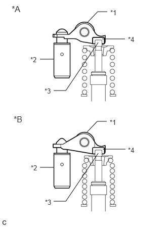
| *A | Type A |
| *B | Type B |
| *1 | No. 1 Valve Rocker Arm Sub-assembly |
| *2 | Valve Lash Adjuster Assembly |
| *3 | Valve Stem |
| *4 | Valve Stem Cap |
Install the 24 No. 1 valve rocker arm sub-assemblies as shown in the illustration.
13053
9.INSTALL NO. 3 CAMSHAFT