STEERING GEAR / LINKAGE STEERING GEAR(When Not Using the Engine Support Bridge for AWD) INSTALLATION
PROCEDURE

 45470
1.INSTALL TIE ROD ASSEMBLY LH
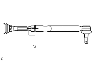
| *a | Matchmark |
Install the lock nut and tie rod assembly LH to the steering gear assembly until the matchmarks are aligned.
- HINT:
-
After adjusting the toe-in, tighten the lock nut.
45460
2.INSTALL TIE ROD ASSEMBLY RH
- HINT:
-
Perform the same procedure as for the LH side.
3.INSTALL STEERING LINK ASSEMBLY
Install the steering link assembly to the front frame assembly with the 2 bolts and 2 nuts.
- Torque:
- 70 N*m (714 kgf*cm, 52 ft.*lbf)
- NOTICE:
- ·
Make sure to tighten the bolts starting from the steering link assembly pinion shaft side.
·Keep the nut from rotating while turning the bolt because the nut has its own stopper.
48811
4.INSTALL FRONT STABILIZER BAR
Install the front stabilizer bar with 2 front stabilizer links, 2 front No. 2 stabilizer brackets and 2 front No. 1 stabilizer bar bushings to the front frame assembly.
48829A
5.INSTALL FRONT NO. 1 STABILIZER BRACKET LH
48824A
6.INSTALL FRONT NO. 1 STABILIZER BRACKET RH
- HINT:
-
Perform the same procedure as for the LH side.
7.INSTALL ENGINE ASSEMBLY WITH TRANSAXLE
45470
8.CONNECT TIE ROD ASSEMBLY LH
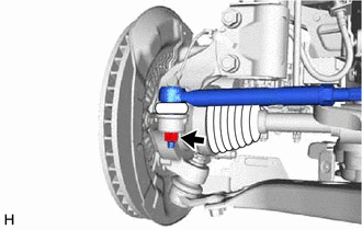
Connect the tie rod assembly LH to the steering knuckle with the nut.
- Torque:
- 49 N*m (500 kgf*cm, 36 ft.*lbf)
- NOTICE:
- ·
Do not damage the ball joint dust cover.
·Further tighten the nut up to 60° if the holes for the cotter pin are not aligned.
Install a new cotter pin.
45460
9.CONNECT TIE ROD ASSEMBLY RH
- HINT:
-
Perform the same procedure as for the LH side.
45220
10.CONNECT STEERING INTERMEDIATE SHAFT ASSEMBLY
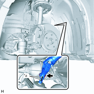
| *a | Matchmark |
Align the matchmarks on the steering intermediate shaft assembly and steering link assembly.
Connect the steering intermediate shaft assembly to the steering link assembly.
Install a new bolt.
- Torque:
- 35.3 N*m (360 kgf*cm, 26 ft.*lbf)
11.INSTALL FRONT WHEELS
- Torque:
- 103 N*m (1050 kgf*cm, 76 ft.*lbf)
12.INSPECT AND ADJUST FRONT WHEEL ALIGNMENT
13.INSPECT STEERING WHEEL CENTER POINT