UA80F AUTOMATIC TRANSMISSION / TRANSAXLE TRANSMISSION CONTROL CABLE INSTALLATION
PROCEDURE

 33820B
1.INSTALL TRANSMISSION CONTROL CABLE ASSEMBLY
- NOTICE:
-
Before installing the transmission control cable assembly, check that the park/neutral position switch assembly and the shift lever are in neutral.
Pass the transmission control cable assembly from the cabin to the engine compartment.
Install the transmission control cable assembly with the 3 bolts.
- Torque:
- 5.0 N*m (51 kgf*cm, 44 in.*lbf)
Install the dash panel insulator to the original position.
Engage the transmission control cable assembly to the No. 3 transmission control cable bracket.
Install a new clip to the No. 1 transmission control cable bracket.
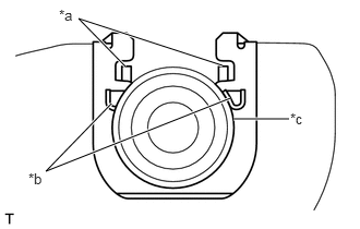
| *a | Claw A |
| *b | Claw B |
| *c | Transmission Control Cable Assembly |
Connect the transmission control cable assembly to the No. 1 transmission control cable bracket.
- NOTICE:
- ·
Make sure that the claws A on the clip are securely fit into the No. 1 transmission control cable bracket holes.
·Make sure that the transmission control cable assembly is securely installed inside of the claws B of the clip.
Connect the transmission control cable assembly to the transmission control shaft lever and install the clip.
- NOTICE:
-
Before connecting the transmission control cable assembly, check that the park/neutral position switch assembly and the shift lever are in neutral.
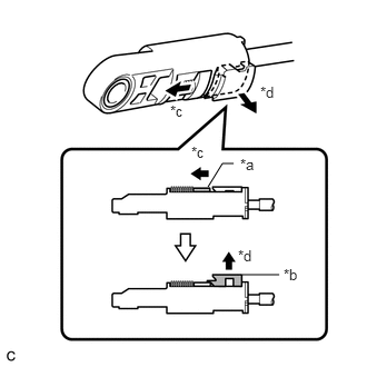
| *a | Slider |
| *b | Lock Piece |
| *c | Slide |
| *d | Pull |
Slide the slider of the transmission control cable assembly in the direction indicated by the arrow in the illustration and pull the lock piece outward.
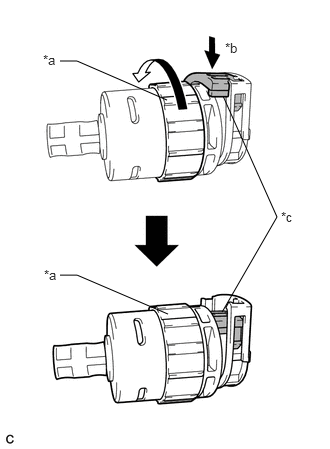
| *a | Lock Nut |
| *b | Push in |
| *c | Stopper |
Turn the lock nut of the transmission control cable assembly counterclockwise. While holding the lock nut, push in the stopper.
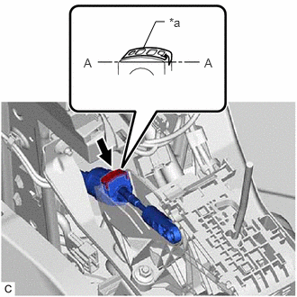
| *a | Stopper |
Install the transmission control cable assembly to the transmission floor shift assembly.
- NOTICE:
-
After installation, check that the outer part of the stopper is protruding beyond portion A-A as shown in the illustration.
| *a | Lock Piece |
| *b | Adjuster Case |
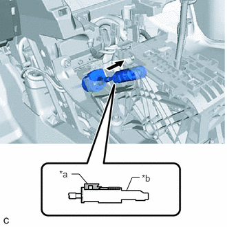
Install the transmission control cable assembly to the transmission floor shift assembly.
- NOTICE:
- ·
Check that the lock piece is pulled out.
·Install the cable end all the way to the base of the transmission floor shift assembly pin.
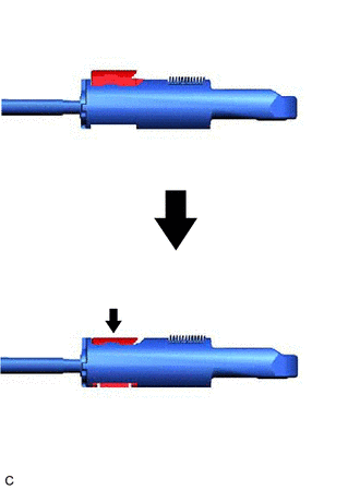
Push the lock piece into the adjuster case.
- NOTICE:
- ·
Check that the park/neutral position switch assembly and shift lever are in neutral.
·Securely push in the lock piece until the slider lock is engaged.
46410
2.CONNECT NO. 1 PARKING BRAKE CABLE ASSEMBLY (for RHD)
Connect the No. 1 parking brake cable assembly with the 3 nuts.
- Torque:
- 6.0 N*m (61 kgf*cm, 53 in.*lbf)
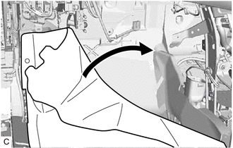
Install the floor carpet to the original position.
3.INSTALL AIR CONDITIONING UNIT ASSEMBLY
17701
4.INSTALL AIR CLEANER CASE SUB-ASSEMBLY
17801
5.INSTALL AIR CLEANER FILTER ELEMENT SUB-ASSEMBLY
17705
6.INSTALL AIR CLEANER CAP WITH AIR CLEANER HOSE
7.INSPECT SHIFT LEVER POSITION
8.ADJUST SHIFT LEVER POSITION