DOOR LOCK REAR DOOR LOCK REMOVAL
CAUTION / NOTICE / HINT
The necessary procedures (adjustment, calibration, initialization, or registration) that must be performed after parts are removed and installed, or replaced during rear door lock with motor assembly removal/installation are shown below.
| Replaced Part or Performed Procedure | Necessary Procedure | Effect/Inoperative Function when Necessary Procedure not Performed | Link |
|---|---|---|---|
|
*1: Learning can also be performed using the GTS. Click here( |
|||
| Disconnect cable from negative auxiliary battery terminal | Perform steering sensor zero point calibration | Lane Control System | ( ) |
| Parking Support Brake System*1 | |||
| Pre-collision System | |||
| Memorize steering angle neutral point | Parking Assist Monitor System | ()
|
|
| Panoramic View Monitor System | ()
|
||
| Initialize back door lock | Power Door Lock Control System | ()
|
|
| Reset back door close position | Power Back Door System | ()
|
|
- NOTICE:
-
After the ignition switch is turned off, the radio and display receiver assembly or the radio receiver assembly records various types of memory and settings. As a result, after turning the ignition switch off, make sure to wait at least 120 seconds before disconnecting the cable from the negative (-) auxiliary battery terminal.
| Replaced Part or Performed Procedure | Necessary Procedure | Effect/Inoperative Function when Necessary Procedure not Performed | Link |
|---|---|---|---|
|
*1: Learning can also be performed using the GTS. Click here( |
|||
| Disconnect cable from negative auxiliary battery terminal | Perform steering sensor zero point calibration | Lane Control System | ()
|
| Parking Support Brake System*1 | |||
| Pre-collision System | |||
| Memorize steering angle neutral point | Parking Assist Monitor System | ()
|
|
| Panoramic View Monitor System | ()
|
||
| Initialize back door lock | Power Door Lock Control System | ()
|
|
| Reset back door close position | Power Back Door System | ()
|
|
- NOTICE:
-
After the ignition switch is turned off, the radio and display receiver assembly or the radio receiver assembly records various types of memory and settings. As a result, after turning the ignition switch off, make sure to wait at least 120 seconds before disconnecting the cable from the negative (-) auxiliary battery terminal.
- HINT:
- ·
Use the same procedure for the RH side and LH side.
·The following procedure is for the LH side.
PROCEDURE

 1. PRECAUTION
- NOTICE:
-
After turning the ignition switch off, waiting time may be required before disconnecting the cable from the negative (-) auxiliary battery terminal. Therefore, make sure to read the disconnecting the cable from the negative (-) auxiliary battery terminal notices before proceeding with work.
58441L
2.REMOVE BATTERY SERVICE HOLE COVER (for HV Model)
3.DISCONNECT CABLE FROM NEGATIVE AUXILIARY BATTERY TERMINAL
for 2GR-FKS:
Click hereGeneral>MAINTENANCE>2GR-FKS BATTERY>REMOVAL
for A25A-FXS, A25B-FXS:
Click hereGeneral>MAINTENANCE>A25A-FXS, A25B-FXS AUXILIARY BATTERY>REMOVAL
4.REMOVE REAR POWER WINDOW REGULATOR SWITCH ASSEMBLY WITH REAR DOOR UPPER ARMREST BASE PANEL
69278C
5.REMOVE REAR DOOR INSIDE HANDLE BEZEL
67604
6.REMOVE REAR DOOR TRIM BOARD SUB-ASSEMBLY
67842E
7.REMOVE REAR DOOR SERVICE HOLE COVER
69060A
8.REMOVE REAR DOOR LOCK WITH MOTOR ASSEMBLY
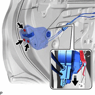
| *a | Release Plate |

|
Remove in this Direction |
Using a T30 "TORX" socket wrench, remove the 3 screws.
Move the rear door lock with motor assembly downward as shown in the illustration to disconnect it from the release plate of the rear door outside handle frame sub-assembly, and remove the rear door lock with motor assembly.
When reusing the rear door lock with motor assembly:
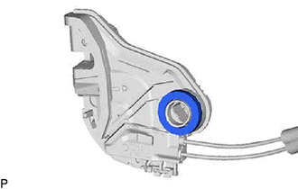
Remove the door lock wiring harness seal from the rear door lock with motor assembly.
69038A
9.REMOVE REAR DOOR LOCK COVER SUB-ASSEMBLY
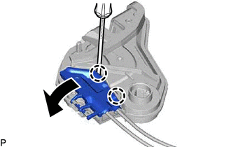
Using a screwdriver, disengage the 2 claws as shown in the illustration.
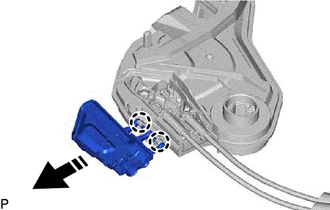
|
|
Remove in this Direction |
Disengage the 2 claws to remove the rear door lock cover sub-assembly as shown in the illustration.
69740D
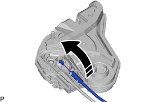
10.REMOVE REAR DOOR LOCK REMOTE CONTROL CABLE ASSEMBLY
|
|
Remove in this Direction |
Remove the rear door lock remote control cable assembly as shown in the illustration.
69780B
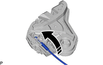
11.REMOVE REAR DOOR INSIDE LOCKING CABLE ASSEMBLY
|
|
Remove in this Direction |
Remove the rear door inside locking cable assembly as shown in the illustration.