Home › Vehicle Exterior › WIPER / WASHER › WIPER AND WASHER SYSTEM
RM37A0E _59 Vehicle Exterior _086901 WIPER / WASHER _0417921 WIPER AND WASHER SYSTEM J

WIPER / WASHER  WIPER AND WASHER SYSTEM  Washer Nozzle Heater Circuit  


DESCRIPTION

The main body ECU controls the washer nozzle sub-assembly and operates the washer nozzle sub-assembly according to the ambient temperature.

WIRING DIAGRAM
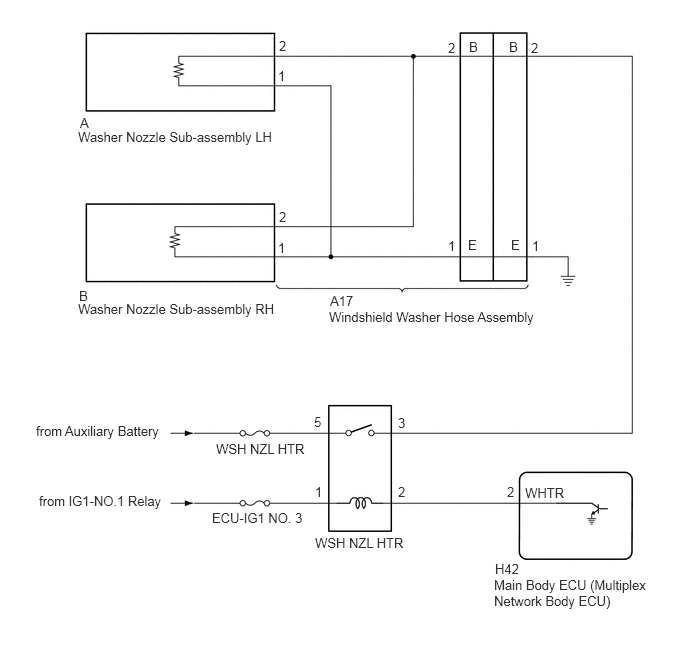
E405259E07
0.375,4.406 2.156,4.74 1.781,0.333 10 false from Auxiliary Battery 2.25,4.594 3.333,4.865 1.083,0.271 10 false WSH NZL HTR 0.406,5.135 1.75,5.365 1.344,0.229 10 false from IG1-NO.1 Relay 2.208,5.313 3.219,5.521 1.01,0.208 10 false ECU-IG1 NO. 3 3.281,5.573 4.896,6.021 1.615,0.448 10 false WSH NZL HTR 5.146,6.01 6.792,6.365 1.646,0.354 10 false Main Body ECU (Multiplex Network Body ECU) 5.469,5.052 6.083,5.25 0.615,0.198 10 false WHTR 3.427,3.219 6.167,3.646 2.74,0.427 10 false Windshield Washer Hose Assembly 5.302,0.406 5.458,0.604 0.156,0.198 10 false B 4.885,0.406 5.042,0.604 0.156,0.198 10 false B 5.323,2.469 5.479,2.667 0.156,0.198 10 false E 4.875,2.469 5.031,2.667 0.156,0.198 10 false E 0.813,1.344 3.063,1.792 2.25,0.448 10 false Washer Nozzle Sub-assembly LH 0.813,3.135 3.292,3.844 2.479,0.708 10 false Washer Nozzle Sub-assembly RH 0.833,1.198 0.99,1.396 0.156,0.198 10 false A 0.823,3 0.979,3.198 0.156,0.198 10 false B 2.906,0.396 3.063,0.594 0.156,0.198 10 false 2 2.906,2.177 3.063,2.375 0.156,0.198 10 false 2 2.896,2.5 3.052,2.698 0.156,0.198 10 false 1 2.896,0.708 3.052,0.906 0.156,0.198 10 false 1 4.667,0.417 4.823,0.615 0.156,0.198 10 false 2 4.667,2.479 4.823,2.677 0.156,0.198 10 false 1 5.531,0.417 5.688,0.615 0.156,0.198 10 false 2 5.542,2.479 5.698,2.677 0.156,0.198 10 false 1 3.438,3.052 3.896,3.25 0.458,0.198 10 false A17 3.271,4.313 3.427,4.51 0.156,0.198 10 false 5 4.146,4.323 4.302,4.521 0.156,0.198 10 false 3 3.281,5.042 3.438,5.24 0.156,0.198 10 false 1 4.146,5.042 4.302,5.24 0.156,0.198 10 false 2 5.281,5.042 5.438,5.24 0.156,0.198 10 false 2 5.156,5.844 5.615,6.042 0.458,0.198 10 false H42

CAUTION / NOTICE / HINT

NOTICE:

Inspect the fuses for circuits related to this system before performing the following inspection procedure.


PROCEDURE

1.PERFORM ACTIVE TEST USING GTS
a.

Disconnect the A17 windshield washer hose assembly connector.


b.

Perform the Active Test according to the display on the GTS.

Body Electrical > Main Body > Active Test
Tester Display Measurement Item Control Range Diagnostic Note
Washer Nozzle Heater Washer nozzle heater operation OFF/ON -
Body Electrical > Main Body > Active Test
Tester Display
Washer Nozzle Heater
50004 123 73

c.

Measure the voltage according to the value(s) in the table below.

Standard Voltage:
Tester Connection Condition Specified Condition
A17-2 (B) - Body ground Ignition switch ON, Active Test is not performed Below 1 V
Ignition switch ON, Active Test is performed 11 to 14 V


Result:
Proceed to
OK
NG


OK

2.INSPECT WASHER NOZZLE SUB-ASSEMBLY

NG

3.INSPECT WSH NZL HTR RELAY
2.INSPECT WASHER NOZZLE SUB-ASSEMBLY
a.

Remove the washer nozzle sub-assembly.

Click hereVehicle Exterior>WIPER / WASHER>WASHER NOZZLE (for Front Side)>REMOVAL


b.

Inspect the washer nozzle sub-assembly.

Click hereVehicle Exterior>WIPER / WASHER>WASHER NOZZLE (for Front Side)>INSPECTION


Result:
Proceed to
OK
NG


OK

REPAIR OR REPLACE HARNESS OR CONNECTOR

NG

REPLACE WASHER NOZZLE SUB-ASSEMBLY

3.INSPECT WSH NZL HTR RELAY
a.

Remove the WSH NZL HTR relay.


b.

Inspect the WSH NZL HTR relay.

Click hereVehicle Exterior>WIPER / WASHER>RELAY>ON-VEHICLE INSPECTION


Result:
Proceed to
OK
NG


OK

4.CHECK HARNESS AND CONNECTOR (WSH NZL HTR RELAY - POWER SOUCE)

NG

REPLACE WSH NZL HTR RELAY

4.CHECK HARNESS AND CONNECTOR (WSH NZL HTR RELAY - POWER SOUCE)
a.

Measure the voltage according to the value(s) in the table below.

Standard Resistance:
Tester Connection Condition Specified Condition
WSH NZL HTR Relay 5 - Body ground Ignition switch off*1
Always*2
11 to 14 V
WSH NZL HTR Relay 1 - Body ground Ignition switch ON 11 to 14 V


·

*1: for HV Model

·

*2: for Gasoline Model


Result:
Proceed to
OK
NG


OK

5.CHECK HARNESS AND CONNECTOR (MAIN BODY ECU (MULTIPLEX NETWORK BODY ECU) - WSH NZL HTR RELAY)

NG

REPAIR OR REPLACE HARNESS OR CONNECTOR

5.CHECK HARNESS AND CONNECTOR (MAIN BODY ECU (MULTIPLEX NETWORK BODY ECU) - WSH NZL HTR RELAY)
a.

Disconnect the H42 main body ECU (multiplex network body ECU) connector.


b.

Measure the resistance according to the value(s) in the table below.

Standard Resistance:
Tester Connection Condition Specified Condition
H42-2 (WHTR) - WSH NZL HTR Relay 2 Ignition switch off*1
Always*2
Below 1 Ω
H42-2 (WHTR) or WSH NZL HTR Relay 2 - Body ground Ignition switch off*1
Always*2
10 kΩ or higher


·

*1: for HV Model

·

*2: for Gasoline Model


Result:
Proceed to
OK
NG


OK

6.CHECK HARNESS AND CONNECTOR (WASHER NOZZLE SUB-ASSEMBLY - WSH NZL HTR RELAY)

NG

REPAIR OR REPLACE HARNESS OR CONNECTOR

6.CHECK HARNESS AND CONNECTOR (WASHER NOZZLE SUB-ASSEMBLY - WSH NZL HTR RELAY)
a.

Measure the resistance according to the value(s) in the table below.

Standard Resistance:
Tester Connection Condition Specified Condition
A17-2 (B) - WSH NZL HTR Relay 3 Ignition switch off*1
Always*2
Below 1 Ω
A17-2 (B) or WSH NZL HTR Relay 3 - Body ground Ignition switch off*1
Always*2
10 kΩ or higher


·

*1: for HV Model

·

*2: for Gasoline Model


Result:
Proceed to
OK
NG


OK

REPLACE MAIN BODY ECU (MULTIPLEX NETWORK BODY ECU)

NG

REPAIR OR REPLACE HARNESS OR CONNECTOR