SLIDING ROOF / CONVERTIBLE SLIDING ROOF HOUSING(for Panoramic Moon Roof) INSTALLATION
PROCEDURE

 1.TEMPORARILY INSTALL SLIDING ROOF HOUSING ASSEMBLY
Temporarily install the sliding roof housing assembly with the 8 nuts.
Tighten the 4 nuts.
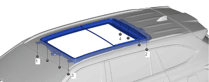
- HINT:
-
Tighten the bolts in the order shown in the illustration.
- Torque:
- 5.5 N*m (56 kgf*cm, 49 in.*lbf)
63246D
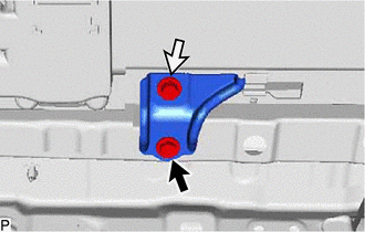
2.INSTALL REAR SLIDING ROOF HOUSING MOUNTING BRACKET LH

|
Bolt (A) |

|
Bolt (B) |
Install the rear sliding roof housing mounting bracket LH with the 2 bolts.
- HINT:
-
The bolts must be tightened in the order of (A) then (B).
- Torque:
- Bolt (A) : 8.0 N*m (82 kgf*cm, 71 in.*lbf)
- Bolt (B) : 5.5 N*m (56 kgf*cm, 49 in.*lbf)
63245D
3.INSTALL REAR SLIDING ROOF HOUSING MOUNTING BRACKET RH
- HINT:
-
Use the same procedure as for the LH side.
63242A
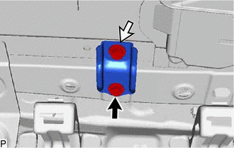
4.INSTALL FRONT SLIDING ROOF HOUSING MOUNTING BRACKET LH
|
|
Bolt (A) |
|
|
Bolt (B) |
Install the front sliding roof housing mounting bracket LH with the 2 bolts.
- HINT:
- ·
Use the same procedure for the front side and rear side.
·The bolts must be tightened in the order of (A) then (B).
- Torque:
- Bolt (A) : 8.0 N*m (82 kgf*cm, 71 in.*lbf)
- Bolt (B) : 5.5 N*m (56 kgf*cm, 49 in.*lbf)
63241A
5.INSTALL FRONT SLIDING ROOF HOUSING MOUNTING BRACKET RH
- HINT:
-
Use the same procedure as for the LH side.
6.INSTALL SLIDING ROOF HOUSING ASSEMBLY
Tighten the 4 nuts to install the sliding roof housing assembly.
- Torque:
- 5.5 N*m (56 kgf*cm, 49 in.*lbf)
63244C
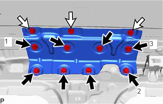
7.INSTALL CENTER SLIDING ROOF HOUSING MOUNTING BRACKET LH
|
|
Bolt (A) |
|
|
Bolt (B) |
Temporarily install the center sliding roof housing mounting bracket LH with the 11 bolts.
Tighten the 3 bolts.
- HINT:
-
Tighten the 3 bolts in the order shown in the illustration.
- Torque:
- 18.5 N*m (189 kgf*cm, 14 ft.*lbf)
Tighten the center sliding roof housing mounting bracket LH with the 8 bolts.
- HINT:
-
The bolts must be tightened in the order of (A) then (B).
- Torque:
- Bolt (A) : 18.5 N*m (189 kgf*cm, 14 ft.*lbf)
- Bolt (B) : 5.5 N*m (56 kgf*cm, 49 in.*lbf)
63243C
8.INSTALL CENTER SLIDING ROOF HOUSING MOUNTING BRACKET RH
- HINT:
-
Use the same procedure as for the LH side.
9.CONNECT SLIDING ROOF DRAIN HOSE
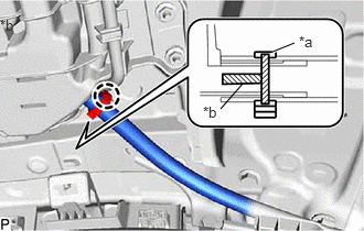
| *a | Clamp |
| *b | Marking |
for Clamp Type:
Connect the sliding roof drain hose.
- HINT:
- ·
Slide the hose to the base of the drain pipe.
·Use the same procedure for the other 3 sliding roof drain hoses.
Engage the claw to secure the sliding roof drain hose.
- HINT:
- ·
Make sure that the clamp is on the marking or between the marking and hose end.
·Use the same procedure for the other 3 sliding roof drain hoses.
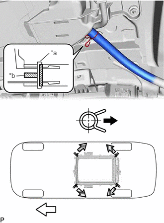
| *a | Clip |
| *b | Marking |
|
|
Outside |
|
|
Front Side |
for Clip Type:
Expand the clip and connect the sliding roof drain hose.
- HINT:
- ·
Slide the hose to the base of the drain pipe.
·Use the same procedure for the other 3 sliding roof drain hoses.
Release the clip to secure the sliding roof drain hose.
- NOTICE:
-
The clip must face toward the outside of the vehicle and also be above the lower surface of the sliding roof housing assembly when installing the sliding roof drain hoses.
- HINT:
- ·
Make sure that the clip is on the marking or between the marking and hose end.
·Use the same procedure for the other 3 sliding roof drain hoses.
62180A
10.INSTALL CURTAIN SHIELD AIRBAG ASSEMBLY LH
62170A
11.INSTALL CURTAIN SHIELD AIRBAG ASSEMBLY RH
- HINT:
-
Use the same procedure as for the LH side.
63201G
12.INSTALL NO. 2 SLIDING ROOF GLASS SUB-ASSEMBLY
Using a T25 "TORX" socket wrench, temporarily install the No. 2 sliding roof glass sub-assembly with the 4 screws.
Perform a level check.
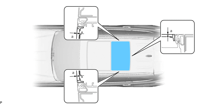
Check the difference in level "a" between the roof panel and the upper surface of the No. 2 sliding roof glass sub-assembly.
- HINT:
-
"+" represents the condition that the glass is above the panel level. "-" represents the condition that the glass is below the panel level.
- Standard:
Area Measurement a 0 + 2.0 mm (0 + 0.0787 in.)
0 - 2.0 mm (0 - 0.0787 in.)
Perform a gap check.
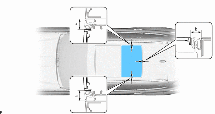
Check the gap between the roof panel and No. 2 sliding roof glass sub-assembly.
- Standard:
Area Measurement a 16.2 mm (0.638 in.) b 16.0 mm (0.630 in.)
After adjusting the No. 2 sliding roof glass sub-assembly, using a T25 "TORX" socket wrench, tighten the 4 screws to install the No. 2 sliding roof glass sub-assembly.
- Torque:
- 4.0 N*m (41 kgf*cm, 35 in.*lbf)
63201G
13.INSTALL NO. 1 SLIDING ROOF GLASS SUB-ASSEMBLY
Using a T25 "TORX" socket wrench, temporarily install the No. 1 sliding roof glass sub-assembly with the 4 screws.
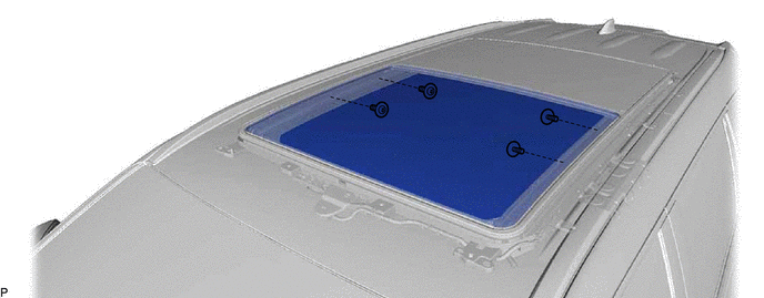
Perform a level check.
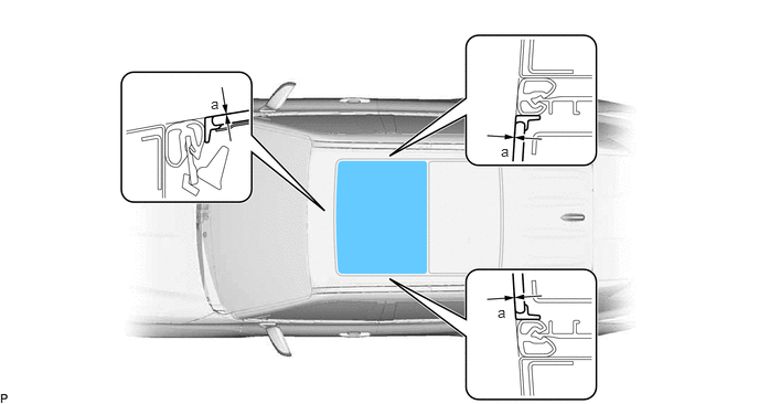
Check the difference in level "a" between the roof panel and the upper surface of the No. 1 sliding roof glass sub-assembly when the No. 1 sliding roof glass sub-assembly is fully closed.
- HINT:
-
"+" represents the condition that the glass is above the panel level. "-" represents the condition that the glass is below the panel level.
- Standard:
Area Measurement a 0 + 2.0 mm (0 + 0.0787 in.)
0 - 2.0 mm (0 - 0.0787 in.)
Perform a gap check.
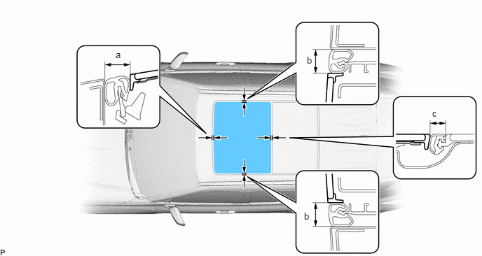
Check the gap between the roof panel and No. 1 sliding roof glass sub-assembly.
- Standard:
Area Measurement a 15.7 mm (0.618 in.) b 16.2 mm (0.638 in.) c 9.5 mm (0.374 in.)
After adjusting the No. 1 sliding roof glass sub-assembly, using a T25 "TORX" socket wrench, tighten the 4 screws.
- Torque:
- 4.0 N*m (41 kgf*cm, 35 in.*lbf)
Check for water leak.
After adjusting the No. 1 sliding roof glass sub-assembly and No. 2 sliding roof glass sub-assembly, check for water leakage into the vehicle interior.
If there are any leaks, readjust the No. 1 sliding roof glass sub-assembly and No. 2 sliding roof glass sub-assembly.
Install the roof headlining assembly.
Click hereVehicle Interior>INTERIOR PANELS / TRIM>ROOF HEADLINING>INSTALLATION
Open the No. 1 sliding roof glass sub-assembly to a position where the 2 screws (A) can be installed.
Using a T25 "TORX" socket wrench, install the No. 1 sliding roof glass sub-assembly with the 2 screws.
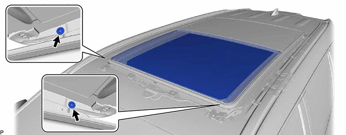
- Torque:
- 4.0 N*m (41 kgf*cm, 35 in.*lbf)
Fully close the No. 1 sliding roof glass sub-assembly.
63218G
14.INSTALL SLIDING ROOF SIDE GARNISH LH
Align the edge of the sliding roof side garnish LH as shown in the illustration.
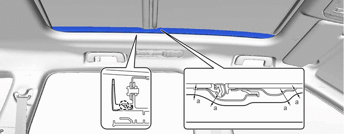
- Standard:
Area Measurement a 1.5 mm (0.0591 in.) or more
Engage the claw to install the sliding roof side garnish LH.
63217G
15.INSTALL SLIDING ROOF SIDE GARNISH RH
- HINT:
-
Use the same procedure as for the LH side.
16.INITIALIZE PANORAMIC MOON ROOF SYSTEM
17.CHECK PANORAMIC MOON ROOF SYSTEM