HYBRID / BATTERY CONTROL SUB RADIATOR INSTALLATION
PROCEDURE

 G9010A
1.INSTALL RADIATOR ASSEMBLY (for Inverter Coolant)
Engage the 2 claws to install the radiator assembly (for inverter coolant) to the radiator assembly.
- NOTICE:
-
Be careful not to damage the radiator assembly (for inverter coolant) or radiator assembly.
Install the 4 bolts.
- Torque:
- 9.0 N*m (92 kgf*cm, 80 in.*lbf)
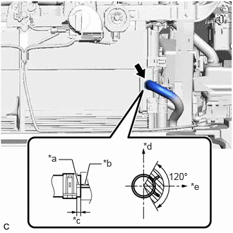
| *a | Alignment Mark |
| *b | Rib |
| *c | 2 to 7 mm (0.0787 to 0.276 in.) |
| *d | Up |
| *e | LH Side |
Connect the No. 4 inverter cooling hose to the radiator assembly (for inverter coolant) and slide the clip to secure it.
- NOTICE:
- ·
To prevent foreign matter from entering the radiator assembly (for inverter coolant) and inverter cooling system, do not remove the pieces of cloth from the pipe and disconnected hose until installation.
·Make sure to align the alignment mark of the hose with the rib of the radiator assembly (for inverter coolant).
·Do not apply excessive force to the No. 4 inverter cooling hose.
- HINT:
-
Make sure that the clip is positioned as shown in the illustration.
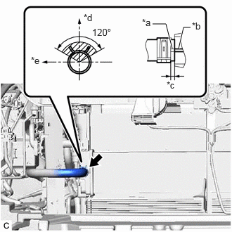
| *a | Alignment Mark |
| *b | Rib |
| *c | 2 to 7 mm (0.0787 to 0.276 in.) |
| *d | Up |
| *e | RH Side |
Connect the No. 3 inverter cooling hose to the radiator assembly (for inverter coolant) and slide the clip to secure it.
- NOTICE:
- ·
To prevent foreign matter from entering the radiator assembly (for inverter coolant) and inverter cooling system, do not remove the pieces of cloth from the pipe and disconnected hose until installation.
·Make sure to align the alignment mark of the hose with the rib of the radiator assembly (for inverter coolant).
·Do not apply excessive force to the No. 3 inverter cooling hose.
- HINT:
-
Make sure that the clip is positioned as shown in the illustration.
16593B
2.INSTALL NO. 1 RADIATOR AIR GUIDE RH
16595B
3.INSTALL NO. 1 RADIATOR AIR GUIDE LH
52021
4.INSTALL FRONT BUMPER REINFORCEMENT SUB-ASSEMBLY
52611
5.INSTALL FRONT BUMPER ENERGY ABSORBER
6.INSTALL HEADLIGHT ASSEMBLY
7.ADD COOLANT (for Inverter)
8.INSPECT FOR COOLANT LEAK (for Inverter)