P810 HYBRID TRANSMISSION / TRANSAXLE HYBRID TRANSAXLE SYSTEM ON-VEHICLE INSPECTION
CAUTION / NOTICE / HINT
- CAUTION:
-
-
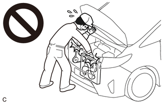
To prevent injury due to contact with an operating V-ribbed belt or cooling fan, keep your hands and clothing away from the V-ribbed belt and cooling fans when working in the engine compartment with the engine running or the ignition switch ON.
PROCEDURE

 1.INSPECT TRANSAXLE FLUID PRESSURE
- NOTICE:
-
Make sure to perform the following inspection after inspecting and adjusting the engine.
Remove the front wheel opening extension pad LH.
Click hereEngine / Hybrid System>A25A-FXS, A25B-FXS (ENGINE MECHANICAL)>ENGINE ASSEMBLY>REMOVAL
Remove the front wheel opening extension pad RH.
Click hereEngine / Hybrid System>A25A-FXS, A25B-FXS (ENGINE MECHANICAL)>ENGINE ASSEMBLY>REMOVAL
Remove the No. 1 engine under cover.
Click hereEngine / Hybrid System>A25A-FXS, A25B-FXS (ENGINE MECHANICAL)>ENGINE ASSEMBLY>REMOVAL
Remove the front fender apron seal LH.
Click hereEngine / Hybrid System>A25A-FXS, A25B-FXS (ENGINE MECHANICAL)>ENGINE ASSEMBLY>REMOVAL
Disconnect the No. 1 transmission oil cooler hose assembly.
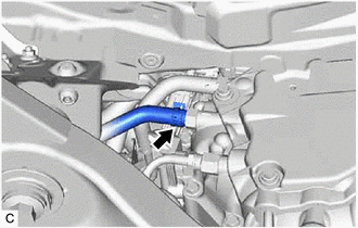
Slide the clip and disconnect the No. 1 transmission oil cooler hose assembly from the tube connector.
Remove the tube connector.
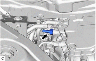
Remove the tube connector from the hybrid vehicle transaxle assembly.
Remove the O-ring from the tube connector.
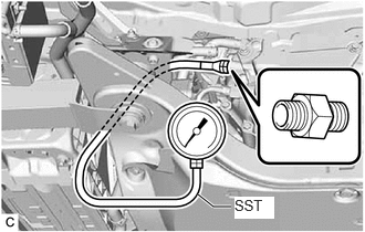
Install SST to the hybrid vehicle transaxle assembly.
- SST
- 09993-19015 (09993-00020, 09993-00050)
Put the engine in Inspection Mode (Maintenance Mode).
Click hereGeneral>INTRODUCTION>REPAIR INSTRUCTION>INSPECTION MODE PROCEDURE
Measure the hybrid transaxle fluid pressure.
- Reference:
Maintenance Mode Engine Idle Speed Hybrid Transaxle Fluid Temperature Hybrid Transaxle Fluid Pressure 900 to 1000 rpm 20 to 50°C (68 to 122°F) 9.8 kPa (0.1 kgf/cm2, 1.4 psi) or more
- NOTICE:
-
Be sure to cancel maintenance mode immediately after the hybrid transaxle fluid pressure check is completed.
Remove SST from the hybrid vehicle transaxle assembly.
Install the tube connector.
Coat a new O-ring with Toyota Genuine ATF WS and install it to the tube connector.
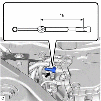
| *a | Torque Wrench Fulcrum Length |
Using a 19 mm ball joint lock nut wrench, install the tube connector to the hybrid vehicle transaxle assembly.
- Torque:
- Specified Tightening Torque : 15 N*m (153 kgf*cm, 11 ft.*lbf)
- HINT:
- ·
Calculate the torque wrench reading when changing the fulcrum length of the torque wrench.
Click hereGeneral>INTRODUCTION>REPAIR INSTRUCTION>PRECAUTION
·When using a 19 mm ball joint lock nut wrench (fulcrum length of 150 mm (5.91 in.)) + torque wrench (fulcrum length of 162 mm (6.38 in.)):
7.8 N*m (80 kgf*cm, 69 in.*lbf)
Connect the No. 1 transmission oil cooler hose assembly.
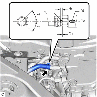
| *a | 0 to 3 mm (0 to 0.118 in.) |
| *b | 2 to 7 mm (0.0787 to 0.276 in.) |
| *c | Paint Mark |
| *d | Marking |
| *e | Center of Paint Mark |
| *f | 45° (Claw of Clip Location) |
Connect the No. 1 transmission oil cooler hose assembly to the tube connector, and slide the clip to secure it.
- NOTICE:
- ·
Make sure to slide the No. 1 transmission oil cooler hose assembly until it contacts the hose stopper of the tube connector.
·Make sure to align the paint mark of the No. 1 transmission oil cooler hose assembly with the marking of the hybrid vehicle transaxle assembly.
·Make sure that the claws of the clip are within the location shown in the illustration.
Install the front fender apron seal LH.
Click hereEngine / Hybrid System>A25A-FXS, A25B-FXS (ENGINE MECHANICAL)>ENGINE ASSEMBLY>INSTALLATION
Install the No. 1 engine under cover.
Click hereEngine / Hybrid System>A25A-FXS, A25B-FXS (ENGINE MECHANICAL)>ENGINE ASSEMBLY>INSTALLATION
Install the front wheel opening extension pad RH.
Click hereEngine / Hybrid System>A25A-FXS, A25B-FXS (ENGINE MECHANICAL)>ENGINE ASSEMBLY>INSTALLATION
Install the front wheel opening extension pad LH.
Click hereEngine / Hybrid System>A25A-FXS, A25B-FXS (ENGINE MECHANICAL)>ENGINE ASSEMBLY>INSTALLATION
2. ROAD TEST
- CAUTION:
-
Confirm the safety of the working environment, then start the inspection.
- NOTICE:
- ·
Perform engine inspection and adjustment before starting a road test.
·Perform a road test at the normal operating fluid temperature: 50 to 80°C (122 to 176°F).
·Make sure the air conditioning switch and cruise control switch are off.
| Check Item | Check Procedure |
| S position test | With the shift lever in S (while the vehicle is stopped), move the shift lever to "+" to check that the shift range indicated on the combination meter changes as follows: 1 → 2, 2 → 3, 3 → 4, 4 → 5 and 5 → 6. |
| Downshifting | While driving with the S3 range selected and a vehicle speed of approximately 84 km/h (52 mph), move the shift lever to "-" and check that the transmission shifts to the S2 range.
|
While driving with the S2 range selected and a vehicle speed of approximately 52 km/h (32 mph), move the shift lever to "-" and check that the transmission shifts to the S1 range.
|
|
| P position test | Stop the vehicle on a grade (more than 5°) and after moving the shift lever to P, release the parking brake and check that the parking lock pawl holds the vehicle in place. |
| Noise and vibration | Check for noise and vibration when driving the vehicle and during gear changes. |
| Fluid leaks | After performing a road test, check for fluid leaks. |