P810 HYBRID TRANSMISSION / TRANSAXLE INPUT SHAFT OIL SEAL REPLACEMENT
CAUTION / NOTICE / HINT
The necessary procedures (adjustment, calibration, initialization or registration) that must be performed after parts are removed and installed, or replaced during input shaft type T oil seal removal/installation are shown below.
| Replaced Part or Performed Procedure | Necessary Procedure | Effect/Inoperative Function when Necessary Procedure not Performed | Link |
|---|---|---|---|
|
*1: Learning can also be performed using the GTS. Click here( *2: Even when not replacing the part, it is necessary to perform the specified necessary procedures after installation. *3: If the vehicle height has changed due to suspension or tire replacement |
|||
| Auxiliary battery terminal is disconnected/reconnected | Perform steering sensor zero point calibration | Lane Control System | ( ) |
| Parking Support Brake System*1 | |||
| Pre-collision System | |||
| Memorize steering angle neutral point | Parking Assist Monitor System | ()
|
|
| Panoramic View Monitor System | ()
|
||
| Initialize back door lock | Power Door Lock Control System | ()
|
|
| Reset back door close position | Power Back Door System | ()
|
|
| Replacement of ECM | Perform Vehicle Identification Number (VIN) registration | DTC is output | ()
|
·
Replacement of engine assembly ·
Gas leak from exhaust system is repaired |
Perform Inspection After Repair | ·
Poor idle, etc. ·
Engine start function, etc. |
()
|
| Replacement of inverter with converter assembly | Resolver learning | ·
DTCs are stored ·
Slight vibration at a vehicle speed of 5 km/h (3 mph) or less ·
Shock or vibration during acceleration |
for 2WD:()
for 4WD/AWD:( )
|
| Front wheel alignment adjustment | Perform "Calibration" | ·
DTCs are stored ·
ABS warning light illuminates ·
Brake system warning light (yellow indicator) illuminates ·
Slip indicator light illuminates ·
VSC disabled or malfunctions |
()
|
| Replacement of front bumper assembly*2 | ·
Measurement of ultrasonic sensor detection angle ·
Ultrasonic sensor detection angle registration |
Parking Support Brake System | ()
|
| Front television camera view adjustment | Panoramic View Monitor System | ()
|
|
Replacement or removal and installation of 2 or more parts:
·
Front television camera assembly, radiator grille sub-assembly or front bumper assembly ·
Rear television camera assembly ·
Side television camera assembly LH or outer rear view mirror assembly LH ·
Side television camera assembly RH or outer rear view mirror assembly RH |
Television camera view adjustment | Panoramic View Monitor System | ()
|
| Suspension, tires, etc.*3 | ·
Measurement of ultrasonic sensor detection angle ·
Ultrasonic sensor detection angle registration |
Parking Support Brake System | ()
|
| Rear television camera assembly optical axis (Back camera position setting) | Parking Assist Monitor System | ()
|
|
·
Parking assist ECU initialization ·
Adjust steering angle |
Panoramic View Monitor System | ()
|
|
- CAUTION:
- ·
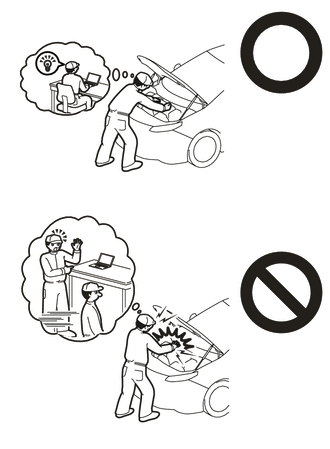
Orange wire harnesses and connectors indicate high-voltage circuits. To prevent electric shock, always follow the procedure described in the repair manual.
for 2WD: Click hereEngine / Hybrid System>HYBRID / BATTERY CONTROL>HYBRID CONTROL SYSTEM (for 2WD)>PRECAUTION
for 4WD/AWD: Click hereEngine / Hybrid System>HYBRID / BATTERY CONTROL>HYBRID CONTROL SYSTEM (for 4WD/AWD)>PRECAUTION
·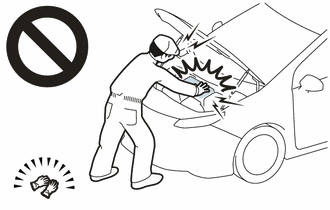
To prevent electric shock, wear insulated gloves when working on wire harnesses and components of the high voltage system.
·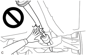
To prevent burns, do not touch the engine, exhaust pipe or other high temperature components while the engine is hot.
- NOTICE:
-
After the ignition switch is turned off, the radio and display receiver assembly or the radio receiver assembly records various types of memory and settings. As a result, after turning the ignition switch off, make sure to wait at least 120 seconds before disconnecting the cable from the negative (-) auxiliary battery terminal.
PROCEDURE

 30900
1.REMOVE HYBRID VEHICLE TRANSAXLE ASSEMBLY
35710A
2.REMOVE INPUT SHAFT TYPE T OIL SEAL
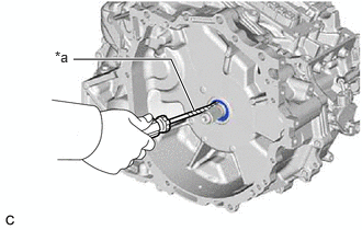
| *a | Protective Tape |
Using a screwdriver with its tip wrapped with protective tape, remove the input shaft type T oil seal from the hybrid vehicle transaxle assembly.
- NOTICE:
-
Be careful not to damage the input shaft assembly or hybrid vehicle transaxle assembly.
35710A
3.INSTALL INPUT SHAFT TYPE T OIL SEAL
Coat the lip of a new input shaft type T oil seal with a small amount of MP grease.
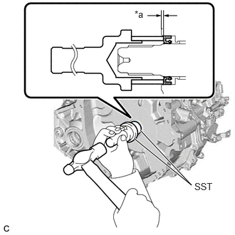
| *a | Depth |
Using SST and a hammer, install the input shaft type T oil seal to the hybrid vehicle transaxle assembly.
- SST
- 09223-22010
09726-10011 (09726-00041)
- Standard Depth:
1.9 to 2.7 mm (0.0748 to 0.106 in.)
- NOTICE:
- ·
Do not allow foreign matter to attach to the lip of the input shaft type T oil seal.
·Do not install the input shaft type T oil seal at an angle.
30900
4.INSTALL HYBRID VEHICLE TRANSAXLE ASSEMBLY