Q610 HYBRID TRANSMISSION / TRANSAXLE REAR TRACTION MOTOR REMOVAL
CAUTION / NOTICE / HINT
The necessary procedures (adjustment, calibration, initialization, or registration) that must be performed after parts are removed and installed, or replaced during rear traction motor with transaxle assembly removal/installation are shown below.
| Replaced Part or Performed Procedure | Necessary Procedure | Effect/Inoperative Function when Necessary Procedure not Performed | Link |
|---|---|---|---|
|
*1: Learning can also be performed using the GTS. Click here( *2: for RH Side *3: If the vehicle height has changed due to suspension or tire replacement |
|||
| Auxiliary battery terminal is disconnected/reconnected | Perform steering sensor zero point calibration | Lane Control System | ( ) |
| Parking Support Brake System*1 | |||
| Pre-collision System | |||
| Memorize steering angle neutral point | Parking Assist Monitor System | ()
|
|
| Panoramic View Monitor System | ()
|
||
| Initialize back door lock | Power Door Lock Control System | ()
|
|
| Reset back door close position | Power Back Door System | ()
|
|
| Gas leaks from exhaust system*2 | Perform Inspection After Repair | ·
Poor idle, etc. ·
Engine start function, etc. |
()
|
| Replacement of rear traction motor with transaxle assembly | ·
Resolver learning ·
Initialize resolver |
·
DTCs are stored ·
Slight vibration at a vehicle speed of 5 km/h (3 mph) or less ·
Shock or vibration during acceleration |
()
|
| Rear wheel alignment adjustment | Perform "Calibration" | ·
DTCs are stored ·
ABS warning light illuminates ·
Brake system warning light (yellow indicator) illuminates ·
Slip indicator light illuminates ·
VSC disabled or malfunctions |
()
|
| Suspension, tires, etc.*3 | ·
Measurement of ultrasonic sensor detection angle ·
Ultrasonic sensor detection angle registration |
Parking Support Brake System | ()
|
| Rear television camera assembly optical axis (Back camera position setting) | Parking Assist Monitor System | ()
|
|
·
Parking assist ECU initialization ·
Adjust steering angle |
Panoramic View Monitor System | ()
|
|
- CAUTION:
- ·
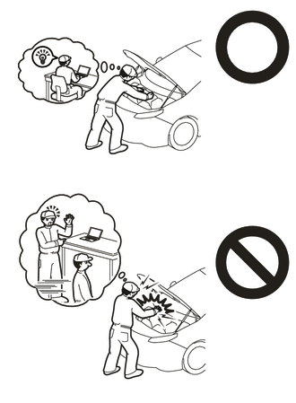
Orange wire harnesses and connectors indicate high-voltage circuits. To prevent electric shock, always follow the procedure described in the repair manual.
Click hereEngine / Hybrid System>HYBRID / BATTERY CONTROL>HYBRID CONTROL SYSTEM (for 4WD/AWD)>PRECAUTION
·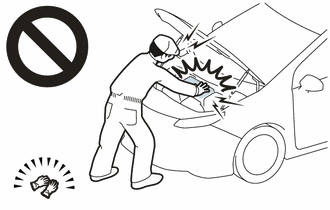
To prevent electric shock, wear insulated gloves when working on wire harnesses and components of the high voltage system.
·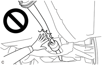
To prevent burns, do not touch the engine, exhaust pipe or other high temperature components while the engine is hot.
- NOTICE:
-
After the ignition switch is turned off, the radio and display receiver assembly or the radio receiver assembly records various types of memory and settings. As a result, after turning the ignition switch off, make sure to wait at least 120 seconds before disconnecting the cable from the negative (-) auxiliary battery terminal.
PROCEDURE

 1. PERFORM RESOLVER INITIALIZATION
- NOTICE:
-
If it is necessary to replace the rear traction motor with transaxle assembly, make sure to perform resolver initialization before starting work.
-
Click hereEngine / Hybrid System>HYBRID / BATTERY CONTROL>MOTOR GENERATOR CONTROL SYSTEM (for 4WD/AWD)>UTILITY
51206A
2.REMOVE REAR SUSPENSION MEMBER SUB-ASSEMBLY
G1050
3.REMOVE REAR TRACTION MOTOR WITH TRANSAXLE ASSEMBLY
Using 2 straps, hold the rear traction motor with transaxle assembly.
- CAUTION:
- ·
Do not lift the rear traction motor with transaxle assembly more than necessary.
·When lifting the rear traction motor with transaxle assembly, make sure it is well balanced.
Remove the 3 bolts, 2 upper differential mount stoppers, 2 lower differential mount stoppers and rear traction motor with transaxle assembly from the rear suspension member sub-assembly.
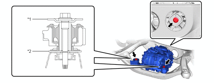
| *1 | Upper Differential Mount Stopper | *2 | Lower Differential Mount Stopper |
- NOTICE:
- ·
Be careful not to drop the rear traction motor with transaxle assembly.
·Be careful not to damage the installation surfaces of the rear traction motor with transaxle assembly when removing it.
4.REMOVE WIRE HARNESS CLAMP BRACKET
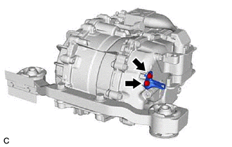
Remove the 2 bolts and wire harness clamp bracket from the rear traction motor with transaxle assembly.
52380F
5.REMOVE FRONT DIFFERENTIAL SUPPORT ASSEMBLY
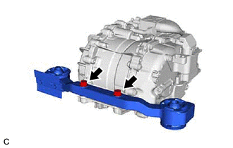
Remove the 2 bolts and front differential support assembly from the rear traction motor with transaxle assembly.
52391D
6.REMOVE DIFFERENTIAL SUPPORT
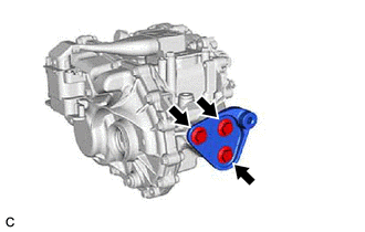
Remove the 3 bolts and differential support from the rear traction motor with transaxle assembly.
G1050C
7.REMOVE REAR TRACTION MOTOR FILLER PLUG
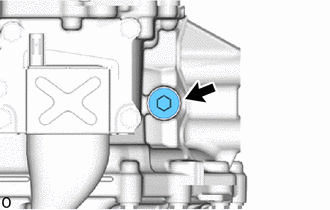
Using a 10 mm hexagon socket wrench, remove the rear traction motor filler plug and gasket from the rear traction motor with transaxle assembly.
52383C
8.REMOVE DIFFERENTIAL SUPPORT PROTECTOR
- HINT:
-
Perform this procedure only when replacement of the differential support protector or front differential support assembly is necessary.
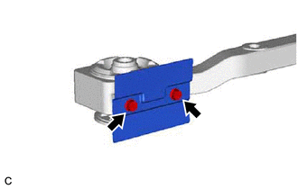
Remove the 2 bolts and differential support protector from the front differential support assembly.