HYBRID / BATTERY CONTROL HYBRID CONTROL SYSTEM(for 4WD/AWD) P0A302A Drive Motor "B" Temperature Sensor Signal Stuck In Range
DTC SUMMARY
MALFUNCTION DESCRIPTION
This DTC is stored when the rear motor temperature sensor output is abnormal.
The cause of this DTC output may be the following:
Rear motor temperature sensor internal malfunction
The connectors are not connected properly
Foreign matter or water on the connector terminals
- HINT:
-
When this DTC is stored, the rear motor temperature sensor is malfunctioning and the self-protection function may not operate. Therefore under certain high load driving condition, the temperature of the rear motor becomes high. If the self-protection function does not operate, the rear motor may malfunction and cause the vehicle to enter fail-safe mode.
DESCRIPTION
Refer to the description for DTC P0A3011.
Click hereEngine / Hybrid System>HYBRID / BATTERY CONTROL>HYBRID CONTROL SYSTEM (for 4WD/AWD)>P0A3011
| DTC No. | Detection Item | DTC Detection Condition | Trouble Area | MIL | Warning Indicate |
|---|---|---|---|---|---|
| P0A302A | Drive Motor "B" Temperature Sensor Signal Stuck In Range | The difference between the maximum and minimum output temperatures of the rear traction motor is less than the stuck malfunction judgment deviation.
(1 trip detection logic) |
·
Wire harness or connector ·
Rear traction motor with transaxle assembly(Rear motor temperature sensor) |
Does not come on | Master Warning: Comes on |
| DTC No. | Data List |
|---|---|
| P0A302A | Rear Motor Temperature |
CONFIRMATION DRIVING PATTERN
- HINT:
-
After repairs have been completed, clear the DTCs and then check that the vehicle has returned to normal by performing the following All Readiness check procedure.
-
Click hereEngine / Hybrid System>HYBRID / BATTERY CONTROL>HYBRID CONTROL SYSTEM (for 4WD/AWD)>UTILITY
Connect the GTS to the DLC3.
Turn the ignition switch to ON and turn the GTS on.
Clear the DTCs (even if no DTCs are stored, perform the clear DTC procedure).
Turn the ignition switch off and wait for 2 minutes or more.
Turn the ignition switch to ON and turn the GTS on.
Drive the vehicle (stop and go driving) on urban roads for approximately 5 minutes. If the Data List item "Rear Motor Temperature" shows both increases and decreases in temperature, suspected areas indicated by this DTC are not malfunctioning.
Enter the following menus: Powertrain / Hybrid Control / Utility / All Readiness.
Check the DTC judgment result.
- HINT:
- ·
If the judgment result shows NORMAL, the system is normal.
·If the judgment result shows ABNORMAL, the system has a malfunction.
·If the judgment result shows INCOMPLETE, perform driving pattern again.
WIRING DIAGRAM
Refer to the wiring diagram for DTC P0A3011.
Click hereEngine / Hybrid System>HYBRID / BATTERY CONTROL>HYBRID CONTROL SYSTEM (for 4WD/AWD)>P0A3011
PROCEDURE
Check for DTCs.
- Powertrain > Hybrid Control > Trouble Codes
- 50001 397
- Result:
Result Proceed to No DTCs are output, or DTCs except the ones in the table below are also output. A Any of the following DTCs are also output. B
| Relevant DTC | |
|---|---|
| P0A3011 | Drive Motor "B" Temperature Sensor Circuit Short to Ground |
| P0A3015 | Drive Motor "B" Temperature Sensor Circuit Short to Battery or Open |
Turn the ignition switch off.
A
B
Click hereEngine / Hybrid System>HYBRID / BATTERY CONTROL>HYBRID CONTROL SYSTEM (for 4WD/AWD)>P0A2A11
- Result:
Result Proceed to OK A NG (The connector is not connected securely.) B NG (The terminals are not making secure contact or are deformed, or water or foreign matter exists in the connector.) C
A
B
C
Disconnect the A31 hybrid vehicle control ECU connector.
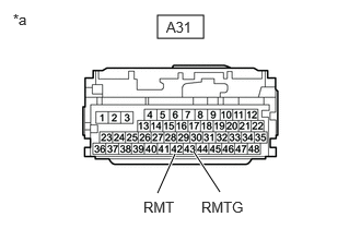
| *a | Front view of wire harness connector
(to Hybrid Vehicle Control ECU) |
Measure the resistance according to the value(s) in the table below.
- Standard Resistance:
Tester Connection Condition Specified Condition A31-42 (RMT) - A31-43 (RMTG) Ignition switch off 0.3443 to 1446 kΩ
Reconnect the A31 hybrid vehicle control ECU connector.
- Result:
Proceed to OK NG
OK
NG
Click hereEngine / Hybrid System>HYBRID / BATTERY CONTROL>HYBRID CONTROL SYSTEM (for 4WD/AWD)>P0A3011
- Result:
Result Proceed to OK A NG (The connector is not connected securely.) B NG (The terminals are not making secure contact or are deformed, or water or foreign matter exists in the connector.) C
A
B
C
Disconnect the AM9 No. 2 floor wire connector.
Disconnect the A31 hybrid vehicle control ECU connector.
Measure the resistance according to the value(s) in the table below.
- HINT:
-
When performing the measurement, lightly jiggle the wire harness up and down and left and right and confirm that the resistance does not fluctuate.
- Standard Resistance (Check for Open):
Tester Connection Condition Specified Condition AM9-10 (RMT) - A31-42 (RMT) Ignition switch off Below 1 Ω AM9-11 (RMTG) - A31-43 (RMTG) Ignition switch off Below 1 Ω
- Standard Resistance (Check for Short):
Tester Connection Condition Specified Condition AM9-10 (RMT) or A31-42 (RMT) - Body ground and other terminals Ignition switch off 10 kΩ or higher AM9-11 (RMTG) or A31-43 (RMTG) - Body ground and other terminals Ignition switch off 10 kΩ or higher
Reconnect the A31 hybrid vehicle control ECU connector.
Reconnect the AM9 No. 2 floor wire connector.
- Result:
Proceed to OK NG
OK
NG
Click hereEngine / Hybrid System>HYBRID / BATTERY CONTROL>HYBRID CONTROL SYSTEM (for 4WD/AWD)>P0A3011
- Result:
Result Proceed to OK A NG (The connector is not connected securely.) B NG (The terminals are not making secure contact or are deformed, or water or foreign matter exists in the connector.) C
A
B
C
Disconnect the NM1 frame wire connector.
Disconnect the AM9 No. 2 floor wire connector.
Measure the resistance according to the value(s) in the table below.
- HINT:
-
When performing the measurement, lightly jiggle the wire harness up and down and left and right and confirm that the resistance does not fluctuate.
- Standard Resistance (Check for Open):
Tester Connection Condition Specified Condition NM1-3 (RMT) - AM9-10 (RMT) Ignition switch off Below 1 Ω NM1-6 (RMTG) - AM9-11 (RMTG) Ignition switch off Below 1 Ω
- Standard Resistance (Check for Short):
Tester Connection Condition Specified Condition NM1-3 (RMT) or AM9-10 (RMT) - Body ground and other terminals Ignition switch off 10 kΩ or higher NM1-6 (RMTG) or AM9-11 (RMTG) - Body ground and other terminals Ignition switch off 10 kΩ or higher
Reconnect the NM1 frame wire connector.
Reconnect the AM9 No. 2 floor wire connector.
- Result:
Proceed to OK NG
OK
NG
Click hereEngine / Hybrid System>HYBRID / BATTERY CONTROL>HYBRID CONTROL SYSTEM (for 4WD/AWD)>P0A3011
- Result:
Result Proceed to OK A NG (The connector is not connected securely.) B NG (The terminals are not making secure contact or are deformed, or water or foreign matter exists in the connector.) C
A
B
C
Disconnect the NM1 frame wire connector.
Remove the rear suspension member sub-assembly.
Click hereSuspension>REAR SUSPENSION>REAR SUSPENSION MEMBER (for HV Model)>REMOVAL
Disconnect the N5 rear motor temperature sensor connector.
Measure the resistance according to the value(s) in the table below.
- Standard Resistance (Check for Open):
Tester Connection Condition Specified Condition N5-2 (RMT) - NM1-3 (RMT) Ignition switch off Below 1 Ω N5-1 (RMTG) - NM1-6 (RMTG) Ignition switch off Below 1 Ω
- Standard Resistance (Check for Short):
Tester Connection Condition Specified Condition N5-2 (RMT) or NM1-3 (RMT) - Body ground and other terminals Ignition switch off 10 kΩ or higher N5-1 (RMTG) or NM1-6 (RMTG) - Body ground and other terminals Ignition switch off 10 kΩ or higher
Reconnect the N5 rear motor temperature sensor connector.
Reinstall the rear suspension member sub-assembly.
Reconnect the NM1 frame wire connector.
- Result:
Proceed to OK NG
OK
NG
Disconnect the AM9 No. 2 floor wire connector.
Measure the resistance according to the value(s) in the table below.
- Standard Resistance:
Tester Connection Condition Specified Condition AM9-10 (RMT) - AM9-11 (RMTG) Ignition switch off 0.3443 to 1446 kΩ
Reconnect the AM9 No. 2 floor wire connector.
- Result:
Proceed to OK NG
OK
NG
Disconnect the NM1 frame wire connector.
Measure the resistance according to the value(s) in the table below.
- Standard Resistance:
Tester Connection Condition Specified Condition NM1-3 (RMT) - NM1-6 (RMTG) Ignition switch off 0.3443 to 1446 kΩ
Reconnect the NM1 frame wire connector.
- Result:
Proceed to OK NG
OK
NG
Click hereEngine / Hybrid System>HYBRID / BATTERY CONTROL>HYBRID CONTROL SYSTEM (for 4WD/AWD)>P0A3011
- Result:
Proceed to OK NG
OK
NG