BRAKE CONTROL / DYNAMIC CONTROL SYSTEMS ELECTRONICALLY CONTROLLED BRAKE SYSTEM(for HV Model) C123D00 IG2 Malfunction
DESCRIPTION
Refer to DTC C110E14.
| DTC No. | Detection Item | DTC Detection Condition | Trouble Area | Note |
|---|---|---|---|---|
| C123D00 | IG2 Malfunction | When communication with the hybrid vehicle control ECU is normal or the vehicle speed is 10 km/h (6 mph) or more, and the IG1 terminal voltage is 10.2 V or more, the IG2 terminal voltage is less than 2.8 V for 4 seconds or more. | ·
Open or short in IG2 circuit ·
Improperly connected connector, deformation or corrosion of terminals ·
No. 1 skid control ECU (brake booster with master cylinder assembly) |
Output ECU: No. 1 skid control ECU (brake booster with master cylinder assembly) |
WIRING DIAGRAM
Refer to DTC C110E14.
CAUTION / NOTICE / HINT
- NOTICE:
- ·
Inspect the fuses for circuits related to this system before performing the following procedure.
·Before performing troubleshooting, make sure to confirm that the auxiliary battery voltage is normal.
Click hereGeneral>INTRODUCTION>HOW TO TROUBLESHOOT ECU CONTROLLED SYSTEMS>HOW TO PROCEED WITH TROUBLESHOOTING
·After replacing the No. 1 skid control ECU (brake booster with master cylinder assembly), perform "Calibration".
PROCEDURE
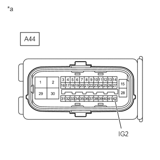
| *a | Front view of wire harness connector
(to No. 1 Skid Control ECU (Brake Booster with Master Cylinder Assembly)) |
Make sure that there is no looseness at the locking part and the connecting part of the connector.
- OK:
The connector is securely connected.
Disconnect the A44 No. 1 skid control ECU (brake booster with master cylinder assembly) connector.
Check both the connector case and the terminals for deformation and corrosion.
- OK:
No deformation or corrosion.
Turn the ignition switch to ON.
Measure the voltage according to the value(s) in the table below.
- Standard Voltage:
Tester Connection Condition Specified Condition A44-42 (IG2) - Body ground Ignition switch ON 11 to 14 V
- Result:
Result Proceed to 11 to 14 V. A Below 11 V. B
A
B