GF2A TRANSFER / 4WD / AWD DYNAMIC TORQUE CONTROL AWD SYSTEM C13F700 4WD/AWD Front Disconnect System Performance
DESCRIPTION
| DTC No. | Detection Item | DTC Detection Condition | Trouble Area | Warning Indicate | Memory |
|---|---|---|---|---|---|
| C13F700 | 4WD/AWD Front Disconnect System Performance | The following conditions occur 5 times or more in succession:
·
When changing from disconnected to connected, the rotation speed of the rear ring gear does not increase for 6 seconds or more after engagement of the front disconnect system starts |
·
Front 4WD linear solenoid (transfer assembly) ·
Transmission revolution sensor |
Displayed | Yes |
WIRING DIAGRAM
Refer to DTC C13ED1C.
Click hereDrivetrain>GF2A (TRANSFER / 4WD / AWD)>DYNAMIC TORQUE CONTROL AWD SYSTEM>C13ED1C
CAUTION / NOTICE / HINT
- NOTICE:
-
After performing repairs, clear the DTCs and check that the DTCs are not output again.
-
Click hereDrivetrain>GF2A (TRANSFER / 4WD / AWD)>DYNAMIC TORQUE CONTROL AWD SYSTEM>DTC CHECK / CLEAR
PROCEDURE
Read the DTCs using the GTS.
- Chassis > Four Wheel Drive > Trouble Codes
- 50001 448
- Result:
Result Proceed to DTC C13ED1C is not output. A DTC C13ED1C is output. B
A
B
Check the transmission revolution sensor installation.
- OK:
The transmission revolution sensor is not deformed or tilted, its installation bolts are tightened to the specified torque, and there is no foreign matter between the transmission revolution sensor and differential carrier assembly.
- Result:
Proceed to OK NG
OK
NG
Remove the transmission revolution sensor.
Connect the battery to the transmission revolution sensor as shown in the illustration.
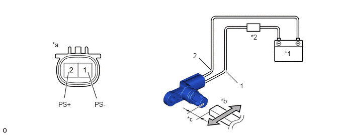
| *1 | Battery | *2 | Ammeter |
| *a | Component without harness connected
(Transmission Revolution Sensor) |
*b | Magnet |
| *c | 5 mm (0.197 in.) | - | - |
Wave a magnet left and right 5 mm (0.197 in.) or less from the tip of the transmission revolution sensor to output a high/low signal while measuring the current.
- NOTICE:
-
Make sure to wave the magnet during the inspection. The current will not change unless the magnet is moved as shown in the illustration.
Measure the current according to the value(s) in the table below.
- Standard Current:
Tester Connection Condition Specified Condition 1 (PS-) - 2 (PS+) Low signal (Move magnet closer) 6 mA 1 (PS-) - 2 (PS+) High signal (Move magnet away) 14 mA
- Result:
Proceed to OK NG
OK
NG