2GR-FKS FUEL FUEL TANK REMOVAL
CAUTION / NOTICE / HINT
The necessary procedures (adjustment, calibration, initialization or registration) that must be performed after parts are removed and installed, or replaced during fuel tank sub-assembly removal/installation are shown below.
| Replaced Part or Performed Procedure | Necessary Procedure | Effect/Inoperative Function when Necessary Procedure not Performed | Link |
|---|---|---|---|
|
*1: Learning can also be performed using the GTS. Click here( *2: If the vehicle height has changed due to suspension or tire replacement |
|||
| Battery terminal is disconnected/reconnected | Idle the engine for approximately 5 to 60 minutes or drive the vehicle until stop and start control is permitted | Stop and Start System | ( ) |
| Perform steering sensor zero point calibration | Lane Control System | ()
|
|
| Parking Support Brake System*1 | |||
| Pre-collision System | |||
| Memorize steering angle neutral point | Parking Assist Monitor System | ()
|
|
| Panoramic View Monitor System | ()
|
||
| Initialize back door lock | Power Door Lock Control System | ()
|
|
| Reset back door close position | Power Back Door System | ()
|
|
| Rear wheel alignment adjustment | 1.
Perform "Reset Memory". 2.
Perform "Calibration". |
·
VSC is disabled or malfunctions ·
DTCs are output ·
Slip indicator light illuminates ·
ABS warning light illuminates |
()
|
| Suspension, tires, etc.*2 | ·
Measurement of ultrasonic sensor detection angle ·
Ultrasonic sensor detection angle registration |
Parking Support Brake System | ()
|
| Rear television camera assembly optical axis (Back camera position setting) | Parking Assist Monitor System | ()
|
|
·
Parking assist ECU initialization ·
Adjust steering angle |
Panoramic View Monitor System | ()
|
|
| Gas leak from exhaust system is repaired | Perform Inspection After Repair | ·
Poor idle, etc. ·
Engine start function, etc. |
()
|
- CAUTION:
- ·
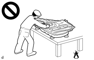
Never perform work on fuel system components near any possible ignition sources.
·Vaporized fuel could ignite, resulting in a serious accident.
·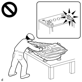
Do not perform work on fuel system components without first disconnecting the cable from the negative (-) battery terminal.
·Sparks could cause vaporized fuel to ignite, resulting in a serious accident.
·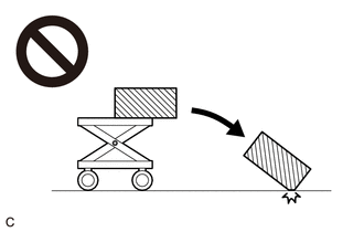
The fuel tank sub-assembly is very heavy. Be sure to follow the procedure described in the repair manual, or the fuel tank sub-assembly may fall off the engine lifter.
- NOTICE:
-
After the ignition switch is turned off, the radio and display receiver assembly or the radio receiver assembly records various types of memory and settings. As a result, after turning the ignition switch off, make sure to wait at least 120 seconds before disconnecting the cable from the negative (-) auxiliary battery terminal.
PROCEDURE

 77020A
1.REMOVE FUEL SUCTION TUBE WITH PUMP AND GAUGE ASSEMBLY
2.DRAIN FUEL
58166A
3.REMOVE FRONT FLOOR COVER LH
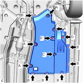
Remove the 4 bolts (A) and 6 screws (B).
Disengage the clip (C) and 2 grommets (D) to remove the front floor cover LH.
58398F
4.REMOVE NO. 1 FLOOR UNDER COVER
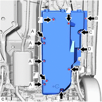
Remove the 4 bolts (A) and screw (B).
Disengage the clip (C), clip (D), clip (E) and 4 grommets (F) to remove the No. 1 floor under cover.
51206A
5.REMOVE REAR SUSPENSION MEMBER SUB-ASSEMBLY
77018E
6.DISCONNECT FUEL TANK EVAPORATION VENT TUBE SUB-ASSEMBLY
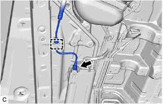
Disengage the clamp and disconnect the fuel tank evaporation vent tube sub-assembly from the canister (charcoal canister assembly).
Click hereEngine / Hybrid System>2GR-FKS (FUEL)>FUEL SYSTEM>PRECAUTION
77209F
7.DISCONNECT FUEL TANK MAIN TUBE SUB-ASSEMBLY
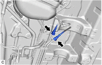
Disconnect the fuel tank main tube sub-assembly from the fuel pipe.
Click hereEngine / Hybrid System>2GR-FKS (FUEL)>FUEL SYSTEM>PRECAUTION
77213B
8.DISCONNECT FUEL TANK TO FILLER PIPE HOSE
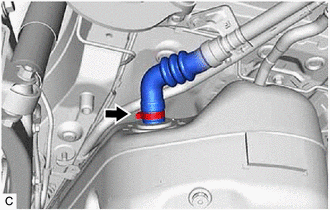
Loosen the clamp, then disconnect the fuel tank to filler pipe hose from the fuel tank sub-assembly.
77001A
9.REMOVE FUEL TANK SUB-ASSEMBLY
- CAUTION:
-
The fuel tank sub-assembly is very heavy. Be sure to follow the procedure described in the repair manual, or the fuel tank sub-assembly may fall off the engine lifter.
for 2WD:
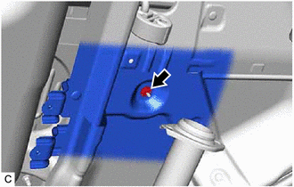
Remove the nut to separate the engine service cover assembly and rear main muffler heat insulator sub-assembly from the vehicle body.
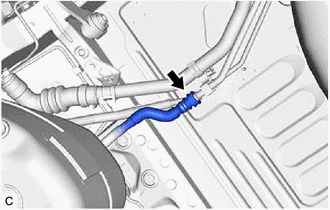
Disconnect the fuel tank breather tube sub-assembly from the fuel tank filler pipe sub-assembly.
Click hereEngine / Hybrid System>2GR-FKS (FUEL)>FUEL SYSTEM>PRECAUTION
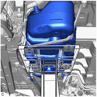
Support the fuel tank sub-assembly using an engine lifter.
- HINT:
-
Using height adjustment attachments and plate lift attachments, keep the fuel tank sub-assembly horizontal.
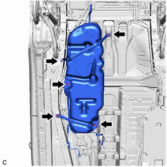
Remove the 5 bolts, No. 1 fuel tank band sub-assembly and No. 2 fuel tank band sub-assembly.
Lower the engine lifter to remove the fuel tank sub-assembly.
- NOTICE:
- ·
Be careful not to drop the fuel tank sub-assembly.
·When removing the fuel tank sub-assembly, tilt it slightly to prevent it from interfering with the surrounding parts.
77209F
10.REMOVE FUEL TANK MAIN TUBE SUB-ASSEMBLY
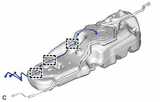
Disengage the 3 clamps to remove the fuel tank main tube sub-assembly from the fuel tank sub-assembly.
77018E
11.REMOVE FUEL TANK EVAPORATION VENT TUBE SUB-ASSEMBLY
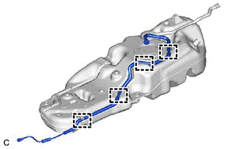
Disengage the 4 clamps to remove the fuel tank evaporation vent tube sub-assembly from the fuel tank sub-assembly.
77285F
12.REMOVE NO. 1 FUEL TUBE CLAMP
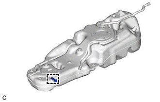
Disengage the clamp to remove the No. 1 fuel tube clamp from the fuel tank sub-assembly.
77642A
13.REMOVE NO. 2 FUEL TANK PROTECTOR
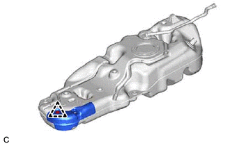
Remove the clip and No. 2 fuel tank protector from the fuel tank sub-assembly.
77656B
14.REMOVE NO. 6 FUEL TANK CUSHION
- HINT:
-
Perform this procedure only when replacement of the No. 6 fuel tank cushion is necessary.
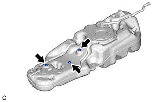
Remove the 3 No. 6 fuel tank cushions from the fuel tank sub-assembly.
77651A
15.REMOVE NO. 1 FUEL TANK CUSHION
- HINT:
-
Perform this procedure only when replacement of the No. 1 fuel tank cushion is necessary.
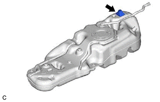
Remove the No. 1 fuel tank cushion from the fuel tank sub-assembly.