UA80E AUTOMATIC TRANSMISSION / TRANSAXLE OIL COOLER INSTALLATION
PROCEDURE

 32907C
1.INSTALL NO. 1 OIL COOLER TUBE SUB-ASSEMBLY WITHOUT HOSE
- HINT:
-
Perform this procedure only when replacement of the No. 1 oil cooler tube sub-assembly without hose is necessary.
Install the inlet No. 1 oil cooler hose, inlet No. 2 oil cooler hose and outlet No. 3 oil cooler hose to the No. 1 oil cooler tube sub-assembly without hose and slide the 3 clips to secure them.
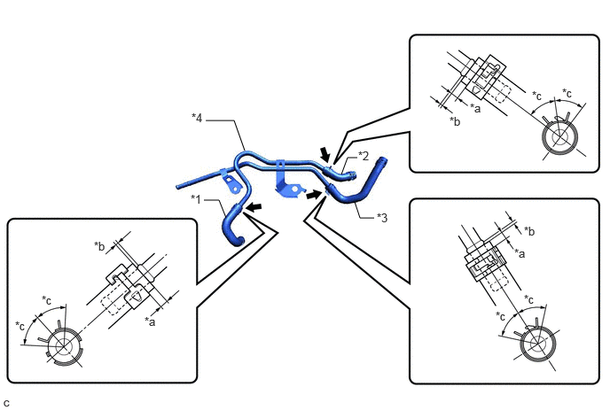
| *1 | Inlet No. 1 Oil Cooler Hose | *2 | Inlet No. 2 Oil Cooler Hose |
| *3 | Outlet No. 3 Oil Cooler Hose | *4 | No. 1 Oil Cooler Tube Sub-assembly without Hose |
| *a | 2 to 7 mm (0.0787 to 0.276 in.) | *b | 0 to 3 mm (0 to 0.118 in.) |
| *c | 45° (Claw of Clip Location) | - | - |
- NOTICE:
- ·
Make sure to slide the inlet No. 1 oil cooler hose, inlet No. 2 oil cooler hose and outlet No. 3 oil cooler hose until each contacts the hose stopper of the No. 1 oil cooler tube sub-assembly without hose.
·Make sure that the claws of each clip are within the location shown in the illustration.
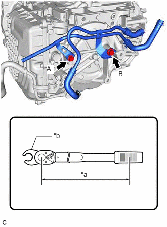
| *a | Torque Wrench Fulcrum Length |
| *b | Union Nut Wrench |
Temporarily install the No. 1 oil cooler tube sub-assembly without hose to the automatic transaxle case sub-assembly with the 2 bolts.
Using a 12 mm union nut wrench, fully tighten the bolt (A).
- Torque:
- Specified Tightening Torque : 13.5 N*m (138 kgf*cm, 10 ft.*lbf)
- HINT:
- ·
Calculate the torque wrench reading when changing the fulcrum length of the torque wrench.
Click hereGeneral>INTRODUCTION>REPAIR INSTRUCTION>PRECAUTION
·When using a 12 mm union nut wrench (fulcrum length of 20 mm (0.787 in.)) + torque wrench (fulcrum length of 162 mm (6.38 in.)):
12 N*m (122 kgf*cm, 9 ft.*lbf)
Using a 14 mm union nut wrench, fully tighten the bolt (B).
- Torque:
- Specified Tightening Torque : 28 N*m (286 kgf*cm, 21 ft.*lbf)
- HINT:
- ·
Calculate the torque wrench reading when changing the fulcrum length of the torque wrench.
Click hereGeneral>INTRODUCTION>REPAIR INSTRUCTION>PRECAUTION
·When using a 14 mm union nut wrench (fulcrum length of 25 mm (0.984 in.)) + torque wrench (fulcrum length of 180 mm (7.09 in.)):
24.6 N*m (251 kgf*cm, 18 ft.*lbf)
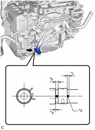
| *a | 0 to 3 mm (0 to 0.118 in.) |
| *b | 2 to 7 mm (0.0787 to 0.276 in.) |
| *c | End of Paint Mark Visible |
| *d | Paint Mark |
Connect the inlet No. 1 oil cooler hose to the oil cooler outlet union or elbow and slide the clip to secure it.
- NOTICE:
- ·
Make sure to slide the inlet No. 1 oil cooler hose until it contacts the hose stopper of the oil cooler outlet union or elbow.
·Make sure that the paint mark of the inlet No. 1 oil cooler hose and clip are within the location shown in the illustration.
32943C
2.CONNECT NO. 3 TRANSMISSION OIL COOLER HOSE
- HINT:
-
Perform this procedure only when replacement of the No. 1 oil cooler tube sub-assembly without hose is necessary.
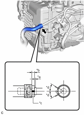
| *a | 0 to 3 mm (0 to 0.118 in.) |
| *b | 2 to 7 mm (0.0787 to 0.276 in.) |
| *c | Paint Mark |
| *d | 30° (Paint Mark Location) |
Connect the No. 3 transmission oil cooler hose to the No. 1 oil cooler tube sub-assembly without hose and slide the clip to secure it.
- NOTICE:
- ·
Make sure to slide the No. 3 transmission oil cooler hose until it contacts the hose stopper of the No. 1 oil cooler tube sub-assembly without hose.
·Make sure that the paint mark of the No. 3 transmission oil cooler hose is within the location shown in the illustration.
·Make sure that the clip is within the location shown in the illustration.
33493A
3.INSTALL TRANSMISSION OIL COOLER
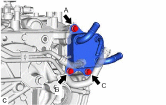
Install the transmission oil cooler to the automatic transaxle case sub-assembly with the 3 bolts.
- Torque:
- 13.5 N*m (138 kgf*cm, 10 ft.*lbf)
- HINT:
-
Tightening order: Temporarily tighten bolt (A) → Fully tighten bolt (B) → Fully tighten bolt (C) → Fully tighten bolt (A)
Engage the wire harness clamp.
32942B
4.CONNECT OUTLET NO. 3 OIL COOLER HOSE
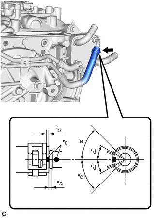
| *a | 0 to 3 mm (0 to 0.118 in.) |
| *b | 2 to 7 mm (0.0787 to 0.276 in.) |
| *c | Paint Mark |
| *d | 30° (Paint Mark Location) |
| *e | 45° (Claw of Clip Location) |
Connect the outlet No. 3 oil cooler hose to the transmission oil cooler and slide the clip to secure it.
- NOTICE:
- ·
Make sure to slide the outlet No. 3 oil cooler hose until it contacts the hose stopper of the transmission oil cooler.
·Make sure to align the paint mark of the outlet No. 3 oil cooler hose with paint mark of the transmission oil cooler.
·Make sure that the paint mark of the outlet No. 3 oil cooler hose and claws of the clip are within the location shown in the illustration.
32941A
5.CONNECT INLET NO. 2 OIL COOLER HOSE
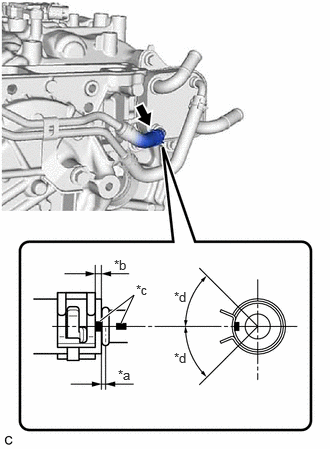
| *a | 0 to 3 mm (0 to 0.118 in.) |
| *b | 2 to 7 mm (0.0787 to 0.276 in.) |
| *c | Paint Mark |
| *d | 45° (Claw of Clip Location) |
Connect the inlet No. 2 oil cooler hose to the transmission oil cooler and slide the clip to secure it.
- NOTICE:
- ·
Make sure to slide the inlet No. 2 oil cooler hose until it contacts the hose stopper of the transmission oil cooler.
·Make sure to align the paint mark of the inlet No. 2 oil cooler hose with the paint mark of the transmission oil cooler.
·Make sure that the claws of the clip are within the location shown in the illustration.
16260
6.CONNECT WATER BY-PASS HOSE ASSEMBLY
Connect the water by-pass hose assembly to the transmission oil cooler and slide the 2 clips to secure it.
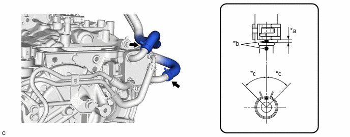
| *a | 2 to 7 mm (0.0787 to 0.276 in.) | *b | Paint Mark |
| *c | 45° (Claw of Clip Location) | - | - |
- NOTICE:
- ·
Make sure to slide the water by-pass hose assembly until it contacts the hose stopper of the transmission oil cooler.
·Make sure to align the paint mark of the water by-pass hose assembly with the paint mark of the transmission oil cooler.
·Make sure that the claws of the clip are within the location shown in the illustration.
33197C
7.INSTALL TRANSMISSION BREATHER CLAMP
Engage the 3 clamps to install the transmission breather clamp.
74404B
8.INSTALL BATTERY CLAMP SUB-ASSEMBLY
9.INSTALL BATTERY
17700
10.INSTALL AIR CLEANER ASSEMBLY WITH AIR CLEANER HOSE
17750A
11.INSTALL INLET AIR CLEANER ASSEMBLY
53295E
12.INSTALL COOL AIR INTAKE DUCT SEAL
13.ADD ENGINE COOLANT
14.ADJUST AUTOMATIC TRANSAXLE FLUID
15.INSPECT FOR COOLANT LEAK
16.INSPECT FOR AUTOMATIC TRANSAXLE FLUID LEAK
53737B
17.INSTALL FRONT FENDER APRON SEAL LH
51444A
18.INSTALL REAR ENGINE UNDER COVER LH
51441
19.INSTALL NO. 1 ENGINE UNDER COVER
53852B
20.INSTALL FRONT WHEEL OPENING EXTENSION PAD LH
53851D
21.INSTALL FRONT WHEEL OPENING EXTENSION PAD RH