HEATING / AIR CONDITIONING REAR AIR CONDITIONING UNIT INSTALLATION
CAUTION / NOTICE / HINT
- NOTICE:
-
To prevent loss of heater effectiveness, make sure the heater water hose is filled with coolant before installing.
PROCEDURE

 87030A
1.INSTALL REAR COOLING UNIT ASSEMBLY
for Gasoline Model:
Engage the guide.
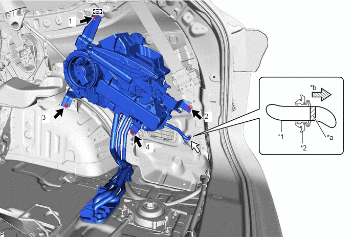
| *1 | Drain Cooler Hose | *2 | Drain Hose Grommet |
| *a | Marking | *b | Insert |
Install the rear cooling unit assembly with the 4 bolts.
- Torque:
- 9.8 N*m (100 kgf*cm, 87 in.*lbf)
- NOTICE:
-
Tighten the bolts in the order shown in the illustration to install the rear cooling unit assembly.
Connect the drain cooler hose as shown in the illustration.
Engage each clamp.
Connect each connector.
for HV Model:
Engage the guide.
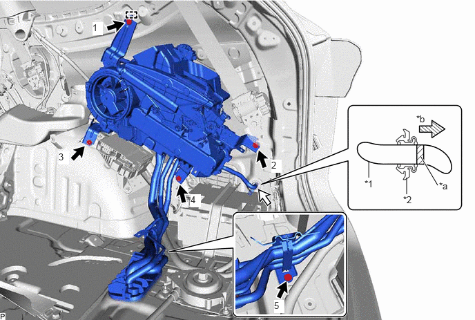
| *1 | Drain Cooler Hose | *2 | Drain Hose Grommet |
| *a | Marking | *b | Insert |
Install the rear cooling unit assembly with the 5 bolts.
- Torque:
- 9.8 N*m (100 kgf*cm, 87 in.*lbf)
- NOTICE:
-
Tighten the bolts in the order shown in the illustration to install the rear cooling unit assembly.
Connect the drain cooler hose as shown in the illustration.
Engage each clamp.
Connect each connector.
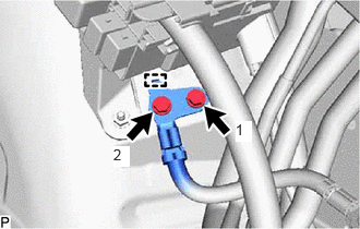
Engage the guide.
Connect the earth wire with the 2 bolts.
- Torque:
- 10 N*m (102 kgf*cm, 7 ft.*lbf)
- NOTICE:
-
Tighten the bolts in the order shown in the illustration.
Install the 2 bolts.
- Torque:
- 5.4 N*m (55 kgf*cm, 48 in.*lbf)
88840D
2.CONNECT NO. 2 AIR CONDITIONING ACCESSORY ASSEMBLY
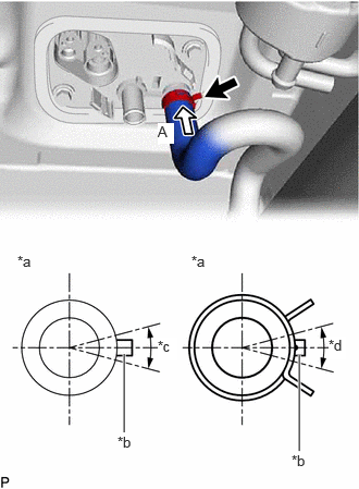
| *a | View A |
| *b | Marking (White) |
| *c | Inlet Heater Water Hose Installation Angle (30°) |
| *d | Clip Installation Angle (60°) |
Connect the inlet heater water hose with the marking within the area shown in the illustration.
- NOTICE:
-
Do not apply excessive force to the inlet heater water hose.
Engage the clip within the area shown in the illustration.
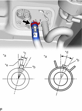
| *a | View A |
| *b | Marking (Yellow) |
| *c | Outlet Heater Water Hose Installation Angle (30°) |
| *d | Clip Installation Angle (60°) |
| *e | 15° |
Connect the outlet heater water hose with the marking within the area shown in the illustration.
- NOTICE:
-
Do not apply excessive force to the outlet heater water hose.
Engage the clip within the area shown in the illustration.
Remove the vinyl tape from the suction tube.
Sufficiently apply compressor oil to a new O-ring and the fitting surface of the suction tube.
| Refrigerant | Compressor Oil |
|---|---|
| for Gasoline Model | ND-OIL 12 or equivalent |
| for HV Model | ND-OIL 11 or equivalent |
Install the O-ring to the suction tube.
- NOTICE:
-
Keep the O-ring and O-ring fitting surface free of foreign matter.
Connect the suction tube with the bolt.
- Torque:
- 5.4 N*m (55 kgf*cm, 48 in.*lbf)
Remove the vinyl tape from the liquid tube.
Sufficiently apply compressor oil to a new O-ring and the fitting surface of the liquid tube.
| Refrigerant | Compressor Oil |
|---|---|
| for Gasoline Model | ND-OIL 12 or equivalent |
| for HV Model | ND-OIL 11 or equivalent |
Install the O-ring to the liquid tube.
- NOTICE:
-
Keep the O-ring and O-ring fitting surface free of foreign matter.
Connect the liquid tube with the bolt.
- Torque:
- 5.4 N*m (55 kgf*cm, 48 in.*lbf)
Install the spare tire.
87217F
3.INSTALL REAR NO. 3 SIDE AIR DUCT
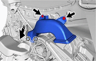

|
Install in this Direction |
Engage the 2 claws as shown in the illustration.
Install the rear No. 3 side air duct with the 2 clips.
87217D
4.INSTALL REAR NO. 1 SIDE AIR DUCT
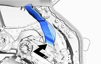
|
|
Install in this Direction |
Install the rear No. 1 side air duct as shown in the illustration.
88892Q
5.INSTALL COOLER PLATE
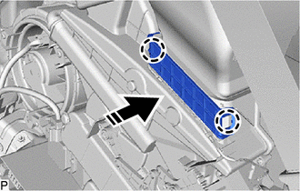
|
|
Install in this Direction |
Engage the 2 claws to install the cooler plate as shown in the illustration.
62470A
6.INSTALL INNER ROOF SIDE GARNISH ASSEMBLY RH
- HINT:
-
Use the same procedure as for the LH side.
-
Click hereVehicle Interior>INTERIOR PANELS / TRIM>ROOF HEADLINING>INSTALLATION
62638A
7.INSTALL QUARTER PILLAR GARNISH RH
- HINT:
-
Use the same procedure as for the LH side.
-
Click hereVehicle Interior>INTERIOR PANELS / TRIM>ROOF HEADLINING>INSTALLATION
64730B
8.INSTALL DECK TRIM SIDE PANEL ASSEMBLY RH
66311
9.INSTALL ROPE HOOK (for RH Side)
- HINT:
-
Use the same procedure as for the LH side.
-
Click hereVehicle Interior>INTERIOR PANELS / TRIM>ROOF HEADLINING>INSTALLATION
64725F
10.INSTALL NO. 1 LUGGAGE COMPARTMENT TRIM HOOK (for RH Side)
- HINT:
-
Use the same procedure as for the LH side.
-
Click hereVehicle Interior>INTERIOR PANELS / TRIM>ROOF HEADLINING>INSTALLATION
64974
11.INSTALL DECK TRIM POCKET COVER (for RH Side)
- HINT:
-
Use the same procedure as for the LH side.
-
Click hereVehicle Interior>INTERIOR PANELS / TRIM>ROOF HEADLINING>INSTALLATION
88625T
12.INSTALL COOLER (NO. 2 ROOM TEMP. SENSOR) THERMISTOR (w/ Rear Automatic Air Conditioning System)
73560
13.CONNECT REAR NO. 2 SEAT OUTER BELT ASSEMBLY RH
- HINT:
-
Use the same procedure as for the LH side.
-
Click hereVehicle Interior>SEAT BELT>REAR NO. 2 SEAT OUTER BELT ASSEMBLY>INSTALLATION
64714H
14.INSTALL NO. 1 DECK SIDE TRIM COVER
- HINT:
-
Use the same procedure as for the No. 2 deck side trim cover.
-
Click hereVehicle Interior>INTERIOR PANELS / TRIM>ROOF HEADLINING>INSTALLATION
73360D
15.CONNECT REAR SEAT OUTER BELT ASSEMBLY RH
- HINT:
-
Use the same procedure as for the LH side.
-
Click hereVehicle Interior>SEAT BELT>REAR NO. 1 SEAT OUTER BELT ASSEMBLY>INSTALLATION
64712F
16.INSTALL FRONT DECK SIDE TRIM COVER RH
62331C
17.CONNECT REAR DOOR OPENING TRIM WEATHERSTRIP RH
67917A
18.INSTALL REAR DOOR SCUFF PLATE RH
- HINT:
-
Use the same procedure as for the LH side.
-
Click hereVehicle Interior>INTERIOR PANELS / TRIM>ROOF HEADLINING>INSTALLATION
72137S
19.INSTALL REAR OUTER SEAT TRACK BRACKET COVER RH
- HINT:
-
Use the same procedure as for the LH side.
-
Click hereVehicle Interior>INTERIOR PANELS / TRIM>ROOF HEADLINING>INSTALLATION
20.INSTALL REAR NO. 2 SEAT ASSEMBLY
58387B
21.INSTALL REAR FLOOR FINISH PLATE
22.ADD ENGINE COOLANT (for Gasoline Model)
23.INSPECT FOR COOLANT LEAK (for Gasoline Model)
24.ADD ENGINE COOLANT (for HV Model)
for Engine:
Click hereGeneral>MAINTENANCE>A25A-FXS, A25B-FXS COOLANT (for Engine)>REPLACEMENT
25.INSPECT FOR COOLANT LEAK (for HV Model)
for Engine:
Click hereEngine / Hybrid System>A25A-FXS, A25B-FXS (COOLING)>COOLING SYSTEM>ON-VEHICLE INSPECTION
26.CHARGE AIR CONDITIONING SYSTEM WITH REFRIGERANT
27.WARM UP ENGINE (for Gasoline Model)
28.WARM UP COMPRESSOR (for HV Model)
29.INSPECT FOR REFRIGERANT LEAK