HEATING / AIR CONDITIONING PTC HEATER ASSEMBLY REMOVAL
CAUTION / NOTICE / HINT
The necessary procedures (adjustment, calibration, initialization or registration) that must be performed after parts are removed and installed, or replaced during quick heater assembly removal/installation are shown below.
| Replaced Part or Performed Procedure | Necessary Procedure | Effect/Inoperative Function when Necessary Procedure not Performed | Link |
|---|---|---|---|
|
*1: Learning can also be performed using the GTS. Click here( |
|||
| Disconnect cable from negative auxiliary battery terminal | Perform steering sensor zero point calibration | Lane Control System | ( ) |
| Parking Support Brake System*1 | |||
| Pre-collision System | |||
| Memorize steering angle neutral point | Parking Assist Monitor System | ()
|
|
| Panoramic View Monitor System | ()
|
||
| Initialize back door lock | Power Door Lock Control System | ()
|
|
| Reset back door close position | Power Back Door System | ()
|
|
- CAUTION:
-
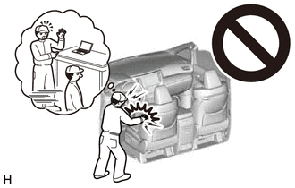
-
Some of these service operations affect the SRS airbag system. Read the precautionary notices concerning the SRS airbag system before servicing.
-
Click hereVehicle Interior>SUPPLEMENTAL RESTRAINT SYSTEMS>AIRBAG SYSTEM>PRECAUTION
- NOTICE:
-
After the ignition switch is turned off, the radio and display receiver assembly or the radio receiver assembly records various types of memory and settings. As a result, after turning the ignition switch off, make sure to wait at least 120 seconds before disconnecting the cable from the negative (-) auxiliary battery terminal.
| Replaced Part or Performed Procedure | Necessary Procedure | Effect/Inoperative Function when Necessary Procedure not Performed | Link |
|---|---|---|---|
|
*1: Learning can also be performed using the GTS. Click here( |
|||
| Disconnect cable from negative auxiliary battery terminal | Idle the engine for approximately 5 to 60 minutes or drive the vehicle until stop and start control is permitted | Stop and Start System | ()
|
| Perform steering sensor zero point calibration | Lane Control System | ()
|
|
| Parking Support Brake System*1 | |||
| Pre-collision System | |||
| Memorize steering angle neutral point | Parking Assist Monitor System | ()
|
|
| Panoramic View Monitor System | ()
|
||
| Initialize back door lock | Power Door Lock Control System | ()
|
|
| Reset back door close position | Power Back Door System | ()
|
|
- CAUTION:
-
-
Some of these service operations affect the SRS airbag system. Read the precautionary notices concerning the SRS airbag system before servicing.
-
Click hereVehicle Interior>SUPPLEMENTAL RESTRAINT SYSTEMS>AIRBAG SYSTEM>PRECAUTION
- NOTICE:
-
After the ignition switch is turned off, the radio and display receiver assembly or the radio receiver assembly records various types of memory and settings. As a result, after turning the ignition switch off, make sure to wait at least 120 seconds before disconnecting the cable from the negative (-) auxiliary battery terminal.
PROCEDURE

 1.REMOVE CONSOLE BOX ASSEMBLY
73900
2.REMOVE LOWER NO. 1 INSTRUMENT PANEL AIRBAG ASSEMBLY
55434F
3.REMOVE LOWER CENTER INSTRUMENT PANEL FINISH PANEL
58816B
4.REMOVE FRONT CONSOLE BOX INSERT
87201L
5.REMOVE NO. 4 AIR DUCT SUB-ASSEMBLY
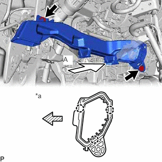
| *a | View A |

|
Front |
Remove the 2 bolts.
Disengage the 3 claws to remove the No. 4 air duct sub-assembly.
- NOTICE:
-
Be careful not to deform or damage the lower heater case of the air conditioner unit assembly when removing the No. 4 air duct sub-assembly.
6.REMOVE PARKING ASSIST ECU WITH BRACKET
87114B
7.REMOVE HEATER COVER
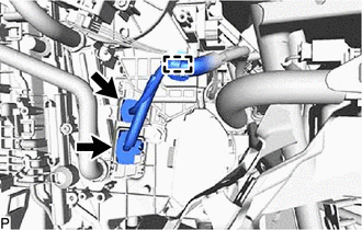
Disconnect the 2 connectors.
Disengage the clamp.
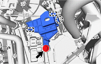
Remove the screw.
Disengage the claw and the 2 guides to remove the heater cover.
87710G
8.REMOVE QUICK HEATER ASSEMBLY
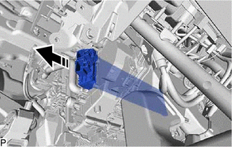

|
Remove in this Direction |
Remove the quick heater assembly as shown in the illustration.