Home › Vehicle Interior › SEAT › SEAT HEATER SYSTEM › from 2021.10
RM37A0E _58 Vehicle Interior _086894 SEAT _0420117 SEAT HEATER SYSTEM J

SEAT  SEAT HEATER SYSTEM  Seat Heater for Front Left Seat does not Operate  


DESCRIPTION

When the seat heater switch of the front seat heater switch (air conditioning control assembly) is operated, the air conditioning amplifier assembly receives a signal and operates the front seat heater.

WIRING DIAGRAM
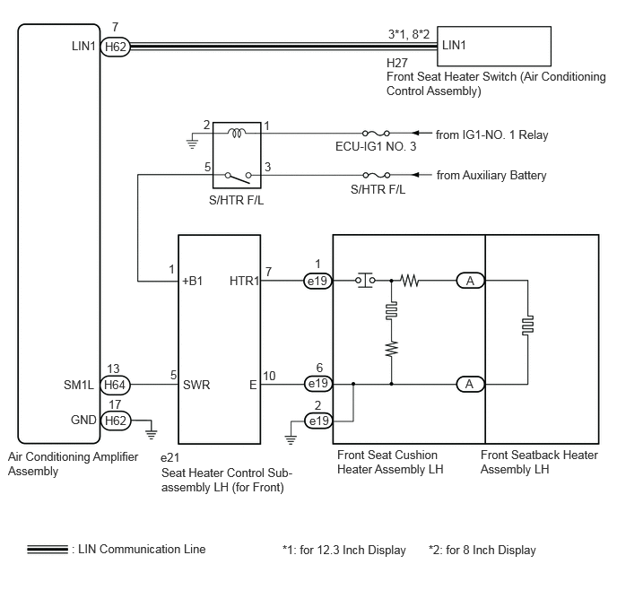
B567558E24
0.833,0.448 1.448,0.646 0.615,0.198 10 false LIN1 1.219,4.802 1.677,5 0.458,0.198 10 false H62 2.427,2.24 3.802,2.438 1.375,0.198 10 false S/HTR F/L 5.063,1.479 7.115,1.823 2.052,0.344 10 false from IG1-NO. 1 Relay 4.49,0.646 4.948,0.844 0.458,0.198 10 false H27 4.49,0.802 7.094,1.146 2.604,0.344 10 false Front Seat Heater Switch (Air Conditioning Control Assembly) 5.135,0.438 5.677,0.729 0.542,0.292 10 false LIN1 2.115,3.177 2.448,3.375 0.333,0.198 10 false +B1 1.865,5.229 2.323,5.427 0.458,0.198 10 false e21 1.875,5.406 3.427,5.979 1.552,0.573 10 false Seat Heater Control Sub-assembly LH (for Front) 3.917,5.198 5.198,5.906 1.281,0.708 10 false Front Seat Cushion Heater Assembly LH 0.094,5.219 1.667,5.854 1.573,0.635 10 false Air Conditioning Amplifier Assembly 0.833,6.292 4.5,6.49 3.667,0.198 10 false : LIN Communication Line 1.26,4.615 1.583,4.958 0.323,0.344 10 false 17 1.979,4.271 2.135,4.469 0.156,0.198 10 false 5 3.073,1.854 3.385,2.052 0.313,0.198 10 false 3 4.51,0.313 5.125,0.531 0.615,0.219 10 false 3*1, 8*2 0.823,4.792 1.281,4.99 0.458,0.198 10 false GND 1.24,4.198 1.688,4.573 0.448,0.375 10 false 13 1.208,4.385 1.667,4.583 0.458,0.198 10 false H64 0.74,4.385 1.198,4.583 0.458,0.198 10 false SM1L 1.958,3.042 2.115,3.24 0.156,0.198 10 false 1 1.219,0.458 1.677,0.656 0.458,0.198 10 false H62 2.125,4.385 2.583,4.583 0.458,0.198 10 false SWR 2.667,3.177 3.104,3.448 0.438,0.271 10 false HTR1 2.896,4.385 3.354,4.583 0.458,0.198 10 false E 3.594,4.802 4.052,5 0.458,0.198 10 false e19 5.583,5.198 6.99,5.771 1.406,0.573 10 false Front Seatback Heater Assembly LH 3.052,4.281 3.323,4.563 0.271,0.281 10 false 10 3.083,3.073 3.24,3.271 0.156,0.198 10 false 7 3.656,2.979 3.813,3.177 0.156,0.198 10 false 1 3.677,4.188 3.833,4.385 0.156,0.198 10 false 6 5.417,3.177 5.875,3.375 0.458,0.198 10 false A 5.406,4.375 5.865,4.573 0.458,0.198 10 false A 3.583,4.365 4.042,4.563 0.458,0.198 10 false e19 3.573,3.177 4.031,3.375 0.458,0.198 10 false e19 3.656,4.625 3.813,4.823 0.156,0.198 10 false 2 4.073,2.115 5.448,2.313 1.375,0.198 10 false S/HTR F/L 3.896,1.615 5.271,1.813 1.375,0.198 10 false ECU-IG1 NO. 3 5.073,1.948 6.792,2.188 1.719,0.24 10 false from Auxiliary Battery 2.365,1.365 2.677,1.563 0.313,0.198 10 false 2 3.063,1.375 3.375,1.573 0.313,0.198 10 false 1 2.375,1.854 2.688,2.052 0.313,0.198 10 false 5 1.302,0.229 1.458,0.427 0.156,0.198 10 false 7 3.281,6.302 5.49,6.51 2.208,0.208 10 false *1: for 12.3 Inch Display 4.979,6.302 6.479,6.531 1.5,0.229 10 false *2: for 8 Inch Display

CAUTION / NOTICE / HINT

NOTICE:
·

If the auxiliary battery voltage is low, the seat heater system may not operate. If "High Power Consumption Power to Climate Temporarily Limited" is displayed on the multi-information display in the combination meter assembly, inspect the auxiliary battery, referring to On-vehicle Inspection of Charging System.

·

If the auxiliary battery voltage becomes low, auxiliary battery load control will operate in order to ensure sufficient power is supplied to the power steering system. In this case, the seat heater system may not operate.

·

Inspect the fuses for circuits related to this system before performing the following procedure.


PROCEDURE

1.CLEAR DTC
a.

Clear the DTCs.

Body Electrical > Air Conditioner > Clear DTCs
50002 121

Result:
Proceed to
NEXT


NEXT

2.CHECK FOR DTC
2.CHECK FOR DTC
a.

Check for DTCs.

Body Electrical > Air Conditioner > Trouble Codes
50001 121
OK:

DTC B14B5 and B14C1 are not output.


Result:
Proceed to
OK
NG


OK

3.PERFORM ACTIVE TEST USING GTS

NG

GO TO DIAGNOSTIC TROUBLE CODE CHART

3.PERFORM ACTIVE TEST USING GTS
a.

Perform the Active Test according to the display on the GTS.

Body Electrical > Air Conditioner > Active Test
Tester Display Measurement Item Control Range Diagnostic Note
Front Left Seat Heater Front seat LH side seat heater operation OFF or ON -
Body Electrical > Air Conditioner > Active Test
Tester Display
Front Left Seat Heater
50004 121 117
OK:

The seat heater operates normally.


Result:
Proceed to
OK
NG


OK

REPLACE FRONT SEAT HEATER SWITCH (AIR CONDITIONING CONTROL ASSEMBLY)

NG

4.CHECK HARNESS AND CONNECTOR (POWER SUPPLY - SEAT HEATER CONTROL SUB-ASSEMBLY LH (FOR FRONT))
a.
B569382C02
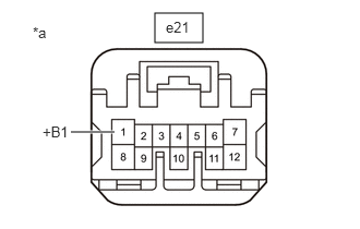
1.479,0.125 1.938,0.406 0.458,0.281 0.677,1.26 1.094,1.26 true 0.313,0.229 0.625,0.385 0.313,0.156 10 false *a 1.583,0.177 2.177,0.469 0.594,0.292 10 false e21 0.406,1.177 0.865,1.375 0.458,0.198 10 false +B1
*a Front view of wire harness connector
(to Seat Heater Control Sub-assembly LH (for Front))


Disconnect the e21 seat heater control sub-assembly LH (for front) connector.

b.

Measure the voltage according to the value(s) in the table below.
Standard Voltage:
Tester Connection Condition Specified Condition
e21-1 (+B1) - Body ground Ignition switch ON 11 to 14 V
e21-1 (+B1) - Body ground Ignition switch off Below 1 V


Result:
Proceed to
OK
NG


OK

5.INSPECT FRONT SEATBACK HEATER ASSEMBLY LH

NG

12.INSPECT S/HTR F/L RELAY
5.INSPECT FRONT SEATBACK HEATER ASSEMBLY LH

OK

6.INSPECT FRONT SEAT CUSHION HEATER ASSEMBLY LH

NG

REPLACE FRONT SEATBACK HEATER ASSEMBLY LH

6.INSPECT FRONT SEAT CUSHION HEATER ASSEMBLY LH

OK

7.CHECK HARNESS AND CONNECTOR (FRONT SEAT CUSHION HEATER ASSEMBLY LH - BODY GROUND)

NG

REPLACE FRONT SEAT CUSHION HEATER ASSEMBLY LH

7.CHECK HARNESS AND CONNECTOR (FRONT SEAT CUSHION HEATER ASSEMBLY LH - BODY GROUND)
a.

Measure the resistance according to the value(s) in the table below.

Standard Resistance:
Tester Connection Condition Specified Condition
e19-2 - Body ground Always Below 1 Ω


Result:
Proceed to
OK
NG


OK

8.CHECK HARNESS AND CONNECTOR (SEAT HEATER CONTROL SUB-ASSEMBLY LH (FOR FRONT) - FRONT SEAT CUSHION HEATER ASSEMBLY LH)

NG

REPAIR OR REPLACE HARNESS OR CONNECTOR

8.CHECK HARNESS AND CONNECTOR (SEAT HEATER CONTROL SUB-ASSEMBLY LH (FOR FRONT) - FRONT SEAT CUSHION HEATER ASSEMBLY LH)
a.

Disconnect the e21 seat heater control sub-assembly LH (for front) connector.


b.

Measure the resistance according to the value(s) in the table below.

Standard Resistance:
Tester Connection Condition Specified Condition
e21-7 (HTR1) - e19-1 Always Below 1 Ω
e21-7 (HTR1) or e19-1 - Body ground Always 10 kΩ or higher
e21-10 (E) - e19-6 Always Below 1 Ω
e21-10 (E) or e19-6 - Body ground Always 10 kΩ or higher


Result:
Proceed to
OK
NG


OK

9.INSPECT SEAT HEATER CONTROL SUB-ASSEMBLY LH (FOR FRONT)

NG

REPAIR OR REPLACE HARNESS OR CONNECTOR

9.INSPECT SEAT HEATER CONTROL SUB-ASSEMBLY LH (FOR FRONT)
a.

Reconnect the e21 seat heater control sub-assembly LH (for front) connector.


b.
B569383C02
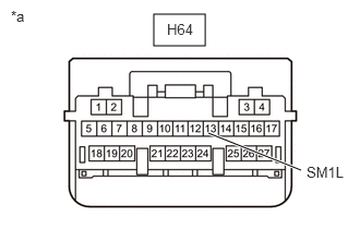
1.469,0.135 1.958,0.438 0.49,0.302 2.875,1.625 1.99,1.271 true 1.594,0.198 2.052,0.396 0.458,0.198 10 false H64 0.104,0.073 0.563,0.271 0.458,0.198 10 false *a 2.927,1.563 3.385,1.76 0.458,0.198 10 false SM1L
*a Front view of wire harness connector
(to Air Conditioning Amplifier Assembly)


Disconnect the H64 air conditioning amplifier assembly connector.


c.

Measure the voltage according to the value(s) in the table below.

Standard Voltage:
Tester Connection Condition Specified Condition
H64-13 (SM1L) - Body ground Ignition switch ON 5 to 13 V


Result:
Proceed to
OK
NG


OK

10.CHECK AIR CONDITIONING AMPLIFIER ASSEMBLY

NG

11.CHECK HARNESS AND CONNECTOR (AIR CONDITIONING AMPLIFIER ASSEMBLY - SEAT HEATER CONTROL SUB-ASSEMBLY LH (FOR FRONT))
10.CHECK AIR CONDITIONING AMPLIFIER ASSEMBLY
a.

Reconnect the e21 seat heater control sub-assembly LH (for front) connector.


b.

Reconnect the H64 air conditioning amplifier assembly connector.


c.

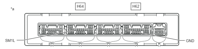
Remove the air conditioning amplifier assembly with its connectors still connected.

Click hereVehicle Interior>HEATING / AIR CONDITIONING>AIR CONDITIONING AMPLIFIER>REMOVAL


d.

Measure the voltage according to the value(s) in the table below.

E435041C02
2.729,0.104 3.083,0.365 0.354,0.26 4.74,0.104 5.094,0.365 0.354,0.26 0.604,1.469 0.844,1.469 0.844,1.469 2.76,1.094 true 4.531,1.094 6.531,1.479 6.531,1.479 6.688,1.479 true 0.385,0.24 0.625,0.521 0.24,0.281 10 false *a 2.781,0.146 3.167,0.417 0.385,0.271 10 false H64 4.792,0.146 5.188,0.427 0.396,0.281 10 false H62 0.188,1.396 0.677,1.646 0.49,0.25 10 false SM1L 6.729,1.406 7.094,1.594 0.365,0.188 10 false GND
*a Component with harness connected
(Air Conditioning Amplifier Assembly)
- -


Standard Voltage:
Tester Connection Condition Specified Condition
H64-13 (SM1L) - H62-17 (GND) Ignition switch ON, front seat heater switch (air conditioning control assembly) on (LO) Below 1 V


Result:
Proceed to
OK
NG


OK

REPLACE SEAT HEATER CONTROL SUB-ASSEMBLY LH

NG

REPLACE AIR CONDITIONING AMPLIFIER ASSEMBLY

11.CHECK HARNESS AND CONNECTOR (AIR CONDITIONING AMPLIFIER ASSEMBLY - SEAT HEATER CONTROL SUB-ASSEMBLY LH (FOR FRONT))
a.

Disconnect the e21 seat heater control sub-assembly LH (for front) connector.


b.

Measure the resistance according to the value(s) in the table below.

Standard Resistance:
Tester Connection Condition Specified Condition
H64-13 (SM1L) - e21-5 (SWR) Always Below 1 Ω
H64-13 (SM1L) or e21-5 (SWR) - Body ground Always 10 kΩ or higher


Result:
Proceed to
OK
NG


OK

REPLACE SEAT HEATER CONTROL SUB-ASSEMBLY LH (FOR FRONT)

NG

REPAIR OR REPLACE HARNESS OR CONNECTOR

12.INSPECT S/HTR F/L RELAY
a.

Inspect the S/HTR F/L relay.

Click hereVehicle Interior>SEAT>RELAY>ON-VEHICLE INSPECTION


Result:
Proceed to
OK
NG


OK

13.CHECK HARNESS AND CONNECTOR (POWER SUPPLY - S/HTR F/L RELAY)

NG

REPAIR OR REPLACE HARNESS OR CONNECTOR

13.CHECK HARNESS AND CONNECTOR (POWER SUPPLY - S/HTR F/L RELAY)
a.

Measure the voltage according to the value(s) in the table below.

Standard Voltage:
Tester Connection Condition Specified Condition
S/HTR F/L relay holder terminal 1 - Body ground Ignition switch ON 11 V to 14 V
S/HTR F/L relay holder terminal 1 - Body ground Ignition switch off Below 1 V
S/HTR F/L relay holder terminal 3 - Body ground Ignition switch off*1
Always*2
11 V to 14 V


*1: for HV Model

*2: for Gasoline Model


Result:
Proceed to
OK
NG


OK

14.CHECK HARNESS AND CONNECTOR (S/HTR F/L RELAY - SEAT HEATER CONTROL SUB-ASSEMBLY LH (FOR FRONT))

NG

REPAIR OR REPLACE HARNESS OR CONNECTOR

14.CHECK HARNESS AND CONNECTOR (S/HTR F/L RELAY - SEAT HEATER CONTROL SUB-ASSEMBLY LH (FOR FRONT))
a.

Measure the resistance according to the value(s) in the table below.

Standard Resistance:
Tester Connection Condition Specified Condition
S/HTR F/L relay holder terminal 5 - e21-1 (+B1) Always Below 1 Ω
S/HTR F/L relay holder terminal 5 or e21-1 (+B1) - Body ground Always 10 kΩ or higher


Result:
Proceed to
OK
NG


OK

15.CHECK HARNESS AND CONNECTOR (S/HTR F/L RELAY - BODY GROUND)

NG

REPAIR OR REPLACE HARNESS OR CONNECTOR

15.CHECK HARNESS AND CONNECTOR (S/HTR F/L RELAY - BODY GROUND)
a.

Measure the resistance according to the value(s) in the table below.

Standard Resistance:
Tester Connection Condition Specified Condition
S/HTR F/L relay holder terminal 2 - Body ground Always Below 1 Ω


Result:
Proceed to
OK
NG


OK

NG

REPAIR OR REPLACE HARNESS OR CONNECTOR