 |
Remove the bolt and clamp.
OIL PUMP (w/ EGR Cooler) > REMOVAL |
| 1. DISCONNECT CABLE FROM NEGATIVE BATTERY TERMINAL |
| 2. REMOVE ENGINE ASSEMBLY |
Remove the engine (Click here).
| 3. REMOVE FUEL INLET PIPE SUB-ASSEMBLY |
|
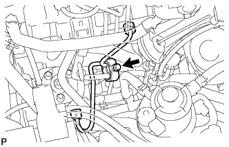
Remove the bolt and clamp.
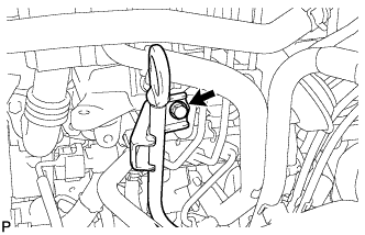 |
Remove the bolt and oil level gauge guide.
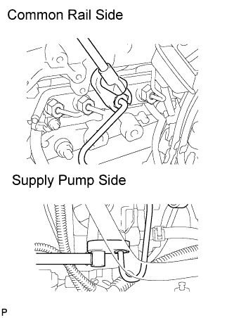 |
Using a 17 mm union nut wrench, loosen the union nuts and remove the fuel inlet pipe.
| 4. REMOVE EGR COOLER WITH ELECTRIC EGR CONTROL VALVE AND NO. 2 EGR VALVE |
Remove the EGR cooler with electric EGR control valve and No. 2 EGR valve (Click here).
| 5. REMOVE NO. 4 INJECTION PIPE |
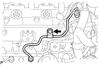 |
Remove the bolt and disconnect the injection pipe clamp.
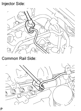 |
Using a 17 mm union nut wrench, loosen the union nuts and remove the No. 4 injection pipe.
| 6. REMOVE VENTILATION PIPE |
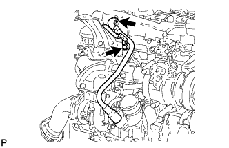 |
Remove the bolt and disconnect the ventilation pipe from the cylinder head cover.
| 7. REMOVE CYLINDER HEAD COVER SUB-ASSEMBLY |
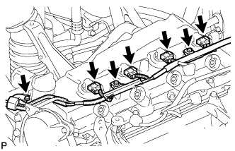 |
Remove the 3 bolts and disconnect the 4 connectors.
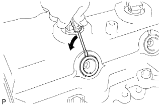 |
Using a small screwdriver, remove the nozzle holder seal by prying the portion between the nozzle holder seal and the cutout part of the cylinder head cover.
Disconnect the ventilation hose.
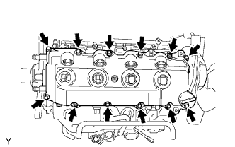 |
Remove the 10 bolts, 2 nuts, cylinder head cover and cylinder head cover gasket.
| 8. REMOVE TIMING BELT |
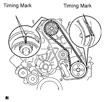 |
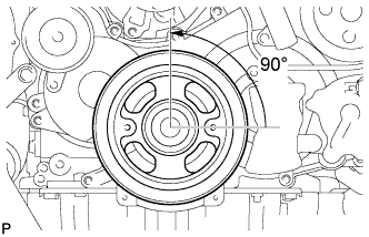
Turn the crankshaft clockwise and align the timing marks as shown in the illustration.
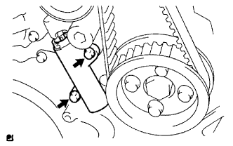 |
Uniformly loosen the 2 bolts and remove the timing belt tensioner.
Remove the timing belt.
Using a 10 mm hexagon wrench, remove the bolt, timing belt idler and washer.
 |
| 9. REMOVE CAMSHAFT TIMING PULLEY |
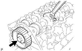 |
Remove the bolt of the camshaft timing pulley by holding the camshaft with a wrench.
Remove the camshaft timing pulley.
| 10. REMOVE NO. 1 TIMING BELT IDLER SUB-ASSEMBLY |
| 11. REMOVE CYLINDER BLOCK INSULATOR |
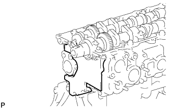 |
Remove the cylinder block insulator form the head.
| 12. REMOVE NO. 2 TIMING BELT COVER |
Remove the 4 bolts, nut and timing belt cover.
| 13. REMOVE WATER PUMP ASSEMBLY |
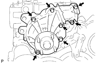 |
Remove the 2 nuts, 5 bolts, water pump and gasket.
| 14. REMOVE TIMING GEAR COVER INSULATOR |
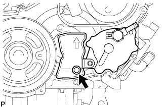 |
Remove the bolt and timing gear cover insulator.
| 15. REMOVE VACUUM PUMP ASSEMBLY |
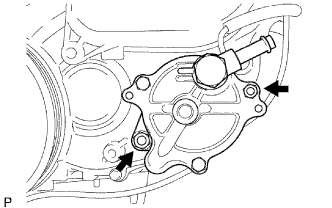 |
Disconnect the vacuum hose.
Remove the 2 nuts, vacuum pump and 2 O-rings.
| 16. REMOVE VANE PUMP ASSEMBLY |
Remove the 2 nuts, vane pump and O-ring.
| 17. REMOVE PUMP DRIVE SHAFT PULLEY |
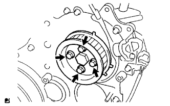 |
Remove the 4 bolts, No. 2 camshaft timing pulley flange and pump drive shaft pulley.
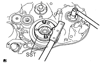 |
Using SST, hold the crankshaft pulley and remove the nut and O-ring.
| 18. REMOVE CRANKSHAFT PULLEY |
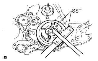 |
Using SST, remove the pulley bolt.
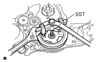 |
Using SST, remove the pulley.
| 19. REMOVE CAMSHAFT POSITION SENSOR |
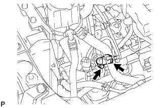 |
Disconnect the sensor connector.
Remove the bolt and sensor.
| 20. REMOVE CRANKSHAFT POSITION SENSOR |
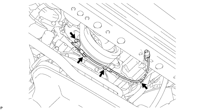
Disconnect the sensor connector.
Remove the 3 clips, bolt and sensor.
| 21. REMOVE TIMING GEAR COVER |
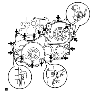 |
Remove the wire harness clamp.
Remove the 14 bolts and 2 nuts.
Using a slotted screwdriver, gently separate the cover from the timing gear case.
Remove the cover and O-ring.
| 22. REMOVE NO. 1 IDLE GEAR |
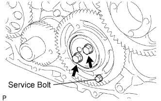 |
Secure the idle gears to the idle gear with the service bolt.
Remove the 2 bolts and thrust plate.
Remove the service bolt.
Turn the sub gear and align the gear teeth of the idle main gear and sub gear.
Remove the idle gear and sub gear.
Remove the idle gear shaft.
| 23. REMOVE CRANKSHAFT TIMING GEAR |
Remove the No. 1 crankshaft sensor plate.
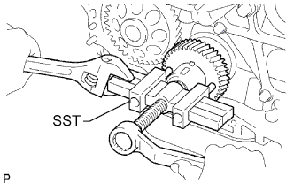 |
Using SST, remove the crankshaft timing gear.
| 24. REMOVE INJECTION GEAR |
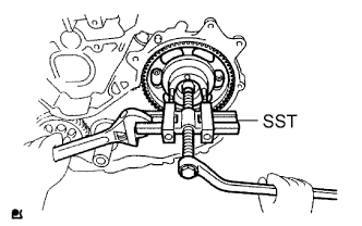 |
Using SST, remove the injection gear.
| 25. REMOVE FUEL SUPPLY PUMP ASSEMBLY |
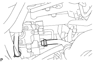 |
Disconnect the 2 fuel hoses.
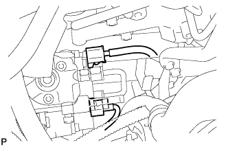 |
Disconnect the 2 connectors.
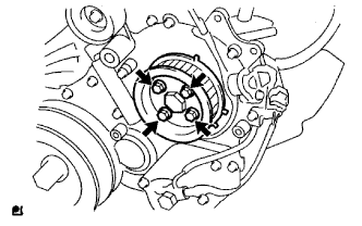 |
Remove the 4 bolts indicated by the arrows in the illustration.
Remove the No. 2 camshaft timing pulley flange and pump drive shaft pulley.
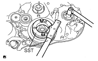 |
Remove the set nut and O-ring while holding the crankshaft pulley by using SST.
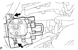 |
Loosen the 2 nuts.
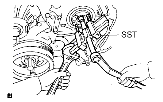 |
Using SST, disconnect the pump from the injection gear.
Remove the 2 nuts and pump.
Remove the O-ring.
| 26. REMOVE OIL DIPSTICK GUIDE |
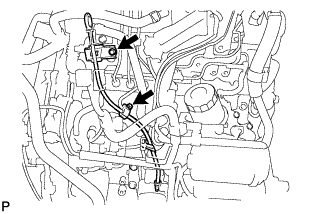 |
Remove the bolt and injection pipe clamp.
Remove the bolt and guide.
Remove the O-ring from the guide.
| 27. REMOVE OIL PAN SUB-ASSEMBLY |
Remove the 22 bolts and 2 nuts.
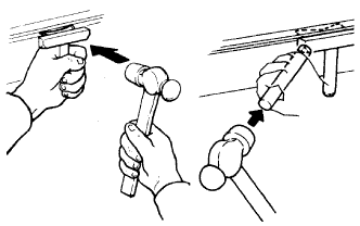 |
Insert the blade of a oil pan seal cutter between the cylinder block and oil pan. Cut through the applied sealer and remove the oil pan.
Remove the 2 bolts, nut, oil strainer and gasket.
Clean off any sealer remaining on the oil pan and cylinder block.
| 28. REMOVE TIMING GEAR CASE ASSEMBLY |
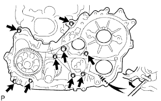 |
Remove the nut and No. 1 vacuum transmitting pipe.
Remove the union bolt and 8 bolts. Then remove the timing gear case and its 2 O-rings.
Remove the oil pump gasket.