MANUAL TRANSMISSION ASSEMBLY > INSTALLATION |
| 1. INSTALL MANUAL TRANSMISSION ASSEMBLY |
|
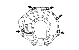
Align the input shaft with the clutch disc and install the transmission to the engine.
Install the 5 bolts.
| 2. INSTALL STIFFENER PLATE |
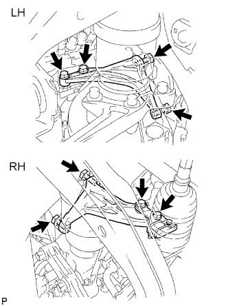 |
Install the stiffener plate RH with the 4 bolts.
Install the stiffener plate LH with the 4 bolts.
| 3. INSTALL REAR NO. 1 ENGINE MOUNTING INSULATOR |
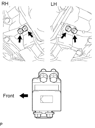 |
Install the mounting insulator with the 4 bolts.
| 4. INSTALL NO. 3 FRAME CROSSMEMBER SUB-ASSEMBLY |
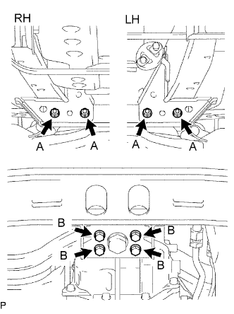 |
Install the frame crossmember with the 4 bolts and 4 nuts.
Install the 4 set bolts to the rear No. 1 engine mounting insulator.
| 5. INSTALL STARTER ASSEMBLY |
| 6. CONNECT CLUTCH RELEASE CYLINDER ASSEMBLY |
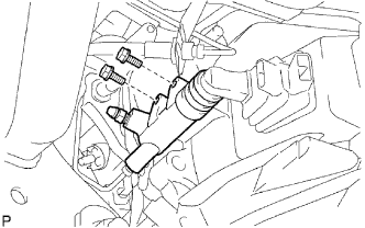 |
Install the clutch release cylinder with the 2 bolts.
| 7. CONNECT WIRE HARNESS |
Connect the back-up light switch connector and speedometer sensor connector.
| 8. INSTALL FRONT EXHAUST PIPE ASSEMBLY |
| 9. INSTALL REAR PROPELLER SHAFT ASSEMBLY |
| 10. INSTALL NO. 2 FRAME CROSSMEMBER SUB-ASSEMBLY |
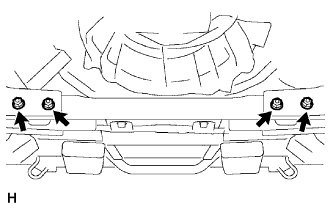 |
Install the frame crossmember with the 4 bolts and 4 nuts.
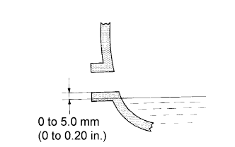
| 11. ADD MANUAL TRANSMISSION OIL |
 |
| 12. INSTALL NO. 2 ENGINE UNDER COVER |
| 13. INSTALL NO. 1 ENGINE UNDER COVER |
| 14. INSTALL FLOOR SHIFT SHIFT LEVER ASSEMBLY |
Cover the shift lever cap with a cloth.
Press down on the shift lever cap and rotate it clockwise to install it.
| 15. INSTALL SHIFT LEVER BOOT ASSEMBLY |
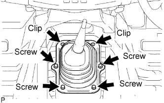 |
Install the shift lever boot with the 4 screws and 2 clips.
| 16. INSTALL CONSOLE BOX ASSEMBLY |
| 17. CONNECT CABLE TO NEGATIVE BATTERY TERMINAL |