PARKING BRAKE CABLE > INSTALLATION |
| 1. INSTALL NO. 3 PARKING BRAKE CABLE ASSEMBLY |
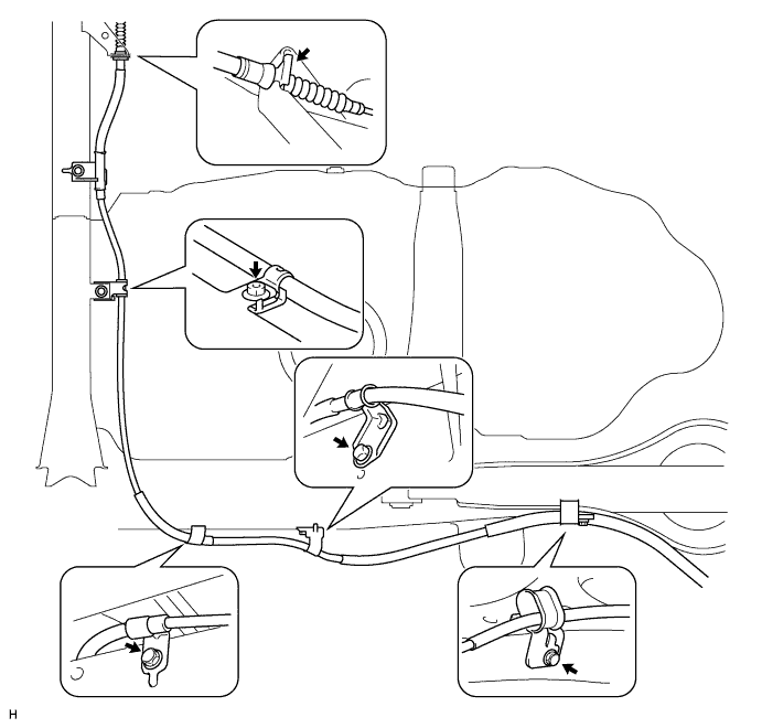
Install the cable with the 4 bolts and nut as shown in the illustration.
Install the No. 3 clip as shown in the illustration.
Connect the cable to the parking brake shoe lever LH and backing plate LH.
Connect the cable to the backing plate with the 2 bolts.
Connect the cable to the lever (Click here).
| 2. INSTALL NO. 2 PARKING BRAKE CABLE ASSEMBLY |
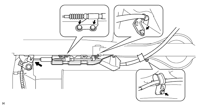
Install the cable with the 4 bolts as shown in the illustration.
Connect the cable to the parking brake shoe lever RH and backing plate RH.
Connect the cable to the backing plate with the 2 bolts.
Connect the cable to the lever (Click here).
Connect the cable to the equalizer as shown in the illustration.
Install the No. 2 heat insulator with the 3 bolts.
| 3. INSTALL NO. 1 PARKING BRAKE CABLE ASSEMBLY |
Connect the cable to the parking brake lever (Click here).
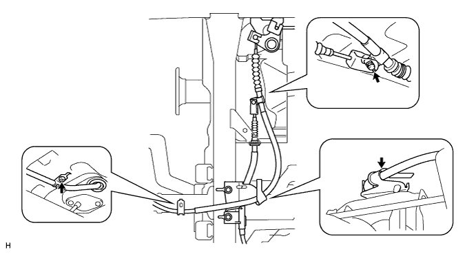
Install the cable with the bolt.
Connect the cable to the equalizer.
Connect the cable to the No. 3 cable.
Install the pin and No. 1 clip.
Attach the cable to the cable support bracket.
Install the No. 1 heat insulator with the 2 bolts.
| 4. CHECK REAR BRAKE DRUM INSTALLATION |
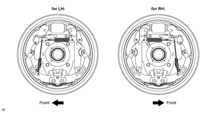
Check that each part is installed properly.
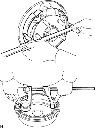 |
Measure the inside diameter of the drum and the diameter of the shoes. Check that the difference between the diameters is the standard shoe clearance.
| 5. INSTALL REAR BRAKE DRUM SUB-ASSEMBLY AND NEW GASKET |
| 6. ADJUST BRAKE SHOE CLEARANCE |
| 7. INSTALL REAR WHEEL |
| 8. CHECK PARKING BRAKE LEVER TRAVEL |
Pull the lever upward with a force of approximately 200 N (20 kgf, 45 lbf) and count the number of clicks.
| 9. ADJUST PARKING BRAKE LEVER TRAVEL |
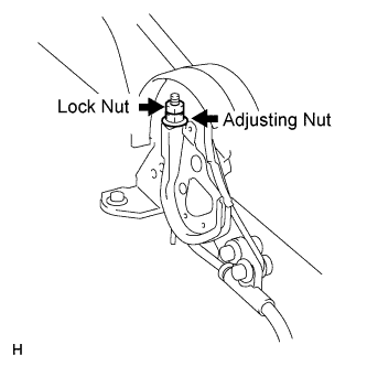 |
Turn the No. 1 wire adjusting nut until the lever travel is correct.
Tighten the lock nut.
| 10. ADJUST PARKING BRAKE TURN BUCKLE |
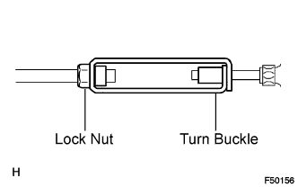 |
Loosen the lock nut and turn buckle until the lever travel is correct.
Tighten the lock nut.
| 11. INSTALL CONSOLE BOX ASSEMBLY |
Install the console box assembly (Click here).
| 12. CONNECT CABLE TO NEGATIVE BATTERY TERMINAL |