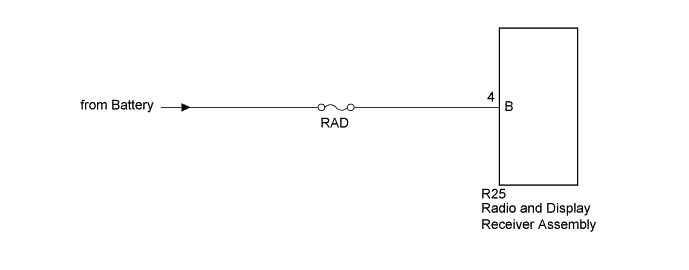
DTC B158F AV Signal Stoppage (Low Battery Voltage) |
| DTC No. | DTC Detection Condition | Trouble Area |
| B158F | A video or audio signal is interrupted when the battery voltage drops. | Radio and display receiver assembly |
| 1.CHECK VEHICLE SIGNAL (OPERATION CHECK) |
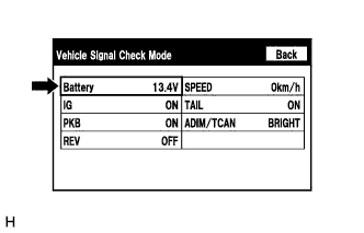 |
Enter the "Vehicle Signal Check Mode" screen. [Refer to Check Vehicle Signal in Operation Check (Click here)]
Check that the battery voltage.
|
| ||||
| OK | |
 |
| 2.CHECK FOR DTC |
Clear the DTCs (Click here).
Check for DTCs (Click here).
|
| ||||
| OK | ||
 | ||
| ||
| 3.CHECK HARNESS AND CONNECTOR (RADIO AND DISPLAY RECEIVER ASSEMBLY POWER SOURCE) |
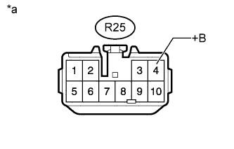 |
Disconnect the radio and display receiver assembly connector.
Measure the voltage according to the value(s) in the table below.
| Tester Connection | Condition | Specified Condition |
| R25-4 (B) - Body ground | Always | 11 to 14 V |
| *a | Front view of wire harness connector (to Radio and Display Receiver Assembly) |
|
| ||||
| OK | ||
| ||
| ||

