ABS Warning Light does not Come ON
Circuit diagnosis · Vehicles built from Jun 2011
DESCRIPTION
If the skid control ECU detects a malfunction, it will prohibit ABS control, illuminate the ABS warning light and store a DTC. Connecting terminals TC and CG of the DLC3 causes the ECU to display DTCs through ABS warning light blinking patterns.WIRING DIAGRAM
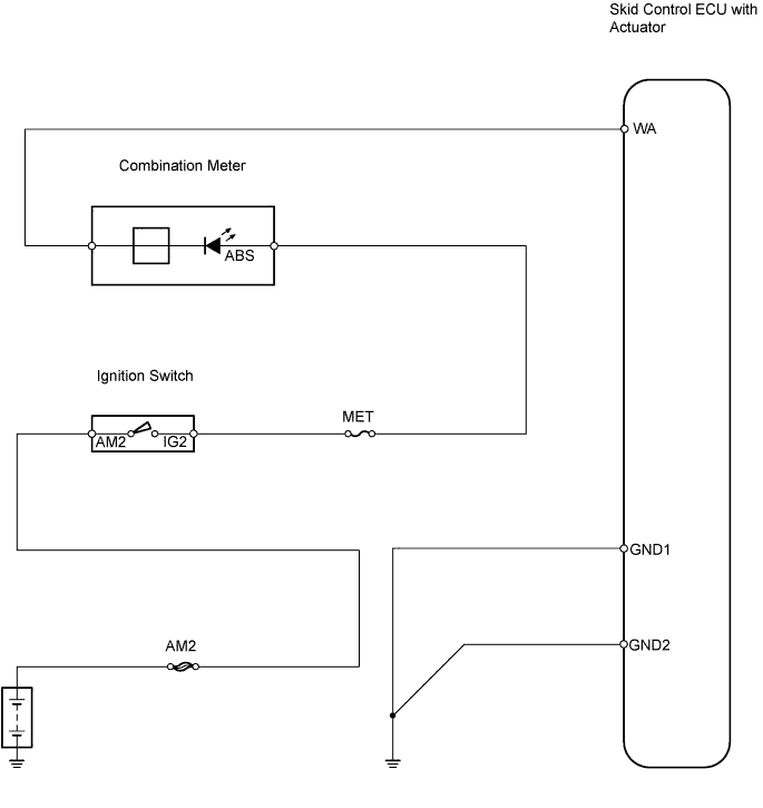

INSPECTION PROCEDURE
| 1. CHOOSE DIAGNOSIS METHOD |

Choose the diagnosis method.
Method Method
Proceed to
Using intelligent tester
A
Not using intelligent tester
B
|
|
||||

| A | |
 |
| 2. PERFORM ACTIVE TEST BY INTELLIGENT TESTER (ABS WARNING LIGHT) |
Select the Active Test, generate a control command, and then check that the ABS warning light operates.
| Item |
Vehicle Condition / Test Details |
Diagnostic Note |
| ABS Warning Light |
Turn ABS warning light ON / OFF |
Observe combination meter |
- OK:
- ABS warning light turns on or off.
|
|
||||

| NG | |
|
| 3. CHECK ABS WARNING LIGHT |
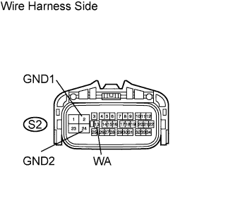 |
Disconnect the S2 ECU connector.
Turn the ignition switch ON.
Using a service wire, connect terminal WA to GND1 or GND2 of the S2 ECU connector. Check the ABS warning light.
- OK:
- ABS warning light turns off.
Turn the ignition switch OFF.
Remove the service wire.
Turn the ignition switch ON. Check the ABS warning light.
- OK:
- ABS warning light illuminates.
|
|
||||
| NG | |
|
| 4. CHECK WIRE HARNESS (SKID CONTROL ECU - COMBINATION METER) |
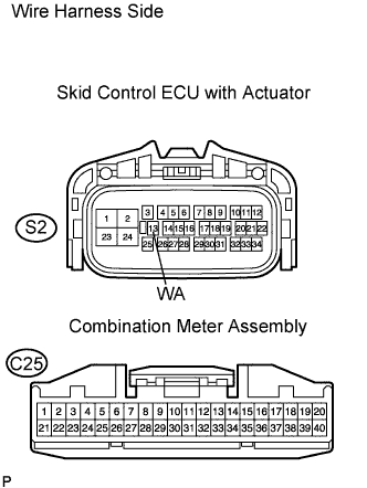 |
Disconnect the S2 ECU connector.
Disconnect the C25 meter connector.
Measure the resistance of the wire harness side connectors.
- Standard resistance:
Tester Connection
Specified Condition
S2-13 (WA) - C25-38
Below 1 Ω
S2-13 (WA) - Body ground
10 kΩ or higher
|
|
||||
| OK | |
|
| 5. CHECK INDICATOR AND WARNING LIGHT |
Check if the indicators and warning lights (SRS, etc.) other than the ABS warning light operate normally.
| Result |
Proceed to |
| Indicators and warning lights operate normally |
A |
| Indicators and warning lights do not operate normally |
B |
|
|
||||
| A | ||
 |
||
| ||