REMOVAL
Removal / installation · Vehicles built from Aug 2013
Versions by build date: Jun 2011 – Jul 2013 from Aug 2013
| 1.
DISCONNECT CABLE FROM NEGATIVE BATTERY TERMINAL |
 |
- CAUTION:
- Wait at least 90 seconds after disconnecting the cable from the negative (-) battery terminal to prevent airbag activation.
| 2.
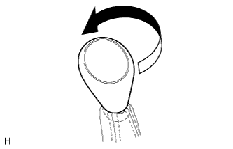
REMOVE SHIFT LEVER KNOB SUB-ASSEMBLY
|
|
Twist the shift lever knob in the direction indicated by the arrow and remove it.
| 3.
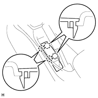
REMOVE PARKING BRAKE HOLE COVER SUB-ASSEMBLY
|
|
Detach the 4 claws and remove the parking brake hole cover.
| 4.
REMOVE UPPER CONSOLE PANEL SUB-ASSEMBLY
|
|
Detach the 12 claws and remove the upper console panel.
- NOTICE:
- Be careful not to damage the instrument panel and console box with the claws of the upper console panel.
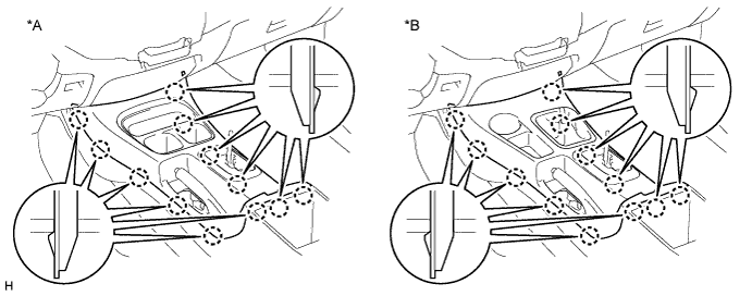

Text in Illustration
*A
|
for 2WD
|
*B
|
for 4WD
|
| 5.
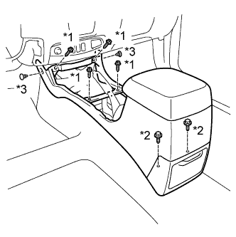
REMOVE CONSOLE BOX ASSEMBLY
|
|
Remove the 4 screws and 2 bolts.
Using a clip remover, remove the 2 clips and console box.
Text in Illustration
*1
|
Screw
|
*2
|
Bolt
|
*3
|
Clip
|
| 6.
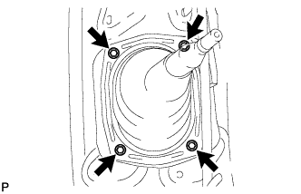
REMOVE SHIFT LEVER BOOT ASSEMBLY |
|
- Remove the 4 screws and shift lever boot.
| 7.
REMOVE TRANSFER HIGH AND LOW SHIFT LEVER ASSEMBLY |
|
- Fold back the transfer front drive shift boot.
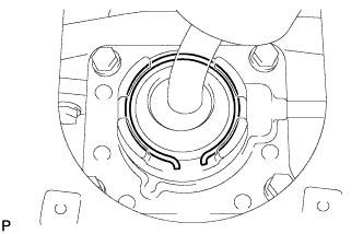
Using needle-nose pliers, remove the snap ring and pull out the shift lever.
- HINT:
- Move the transfer shift lever to the H4 position.
| 8.
REMOVE NO. 1 ENGINE UNDER COVER |
|
| 9.
REMOVE NO. 2 ENGINE UNDER COVER |
|
| 10.
REMOVE NO. 3 ENGINE UNDER COVER |
|
| 11.
REMOVE FRONT EXHAUST PIPE ASSEMBLY |
|
Remove the front exhaust pipe assembly (Click here).
| 12.
REMOVE FRONT PROPELLER SHAFT ASSEMBLY |
|
Remove the front propeller shaft assembly (Click here).
| 13.
REMOVE PROPELLER WITH CENTER BEARING SHAFT ASSEMBLY |
|
Remove the propeller with center bearing shaft assembly (Click here).
| 14.
DRAIN AUTOMATIC TRANSMISSION FLUID |
|
Remove the drain plug and gasket, and drain the ATF.
Install a new gasket and the drain plug.
-
Torque:
- 20 N*m{
205 kgf*cm
, 15 ft.*lbf
}
| 15.
REMOVE TRANSMISSION OIL FILLER TUBE SUB-ASSEMBLY |
|
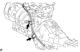
Remove the oil dipstick.
Remove the 2 bolts and oil filler tube.
Remove the O-ring from the oil filler tube.
| 16.
DISCONNECT OIL COOLER TUBE |
|
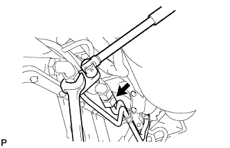
Using a union nut wrench, disconnect the tube outlet and tube inlet.
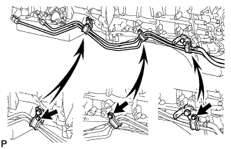
- Remove the 3 bolts and 3 clamps.
| 17.
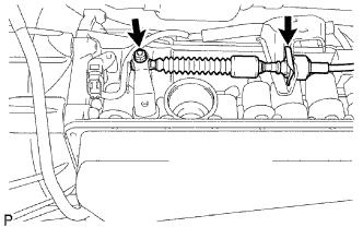
DISCONNECT TRANSMISSION CONTROL CABLE ASSEMBLY |
|
Remove the nut and disconnect the control cable.
Remove the clip and disconnect the control cable.
| 18.
REMOVE FRONT FENDER SEAL
|
|
Remove the 5 clips and seal.
| 19.
REMOVE STARTER ASSEMBLY |
|
Remove the starter assembly (Click here).
| 20.
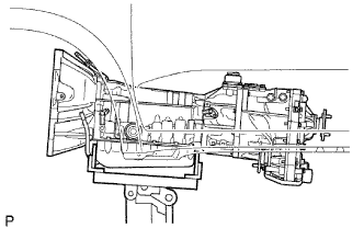
SUPPORT AUTOMATIC TRANSMISSION ASSEMBLY |
|
Support the transmission with a transmission jack.
| 21.
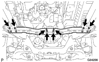
REMOVE NO. 3 FRAME CROSSMEMBER SUB-ASSEMBLY |
|
Remove the 4 set bolts of the rear No. 1 engine mounting insulator.
Remove the 4 nuts, 4 bolts and frame crossmember.
| 22.
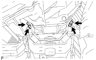
REMOVE REAR NO. 1 ENGINE MOUNTING INSULATOR |
|
Remove the 4 bolts and engine mounting insulator.
| 23.
DISCONNECT CONNECTOR |
|
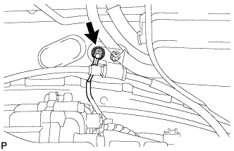
- Remove the nut and disconnect the ground cable.
- Remove the 2 bolts and heat insulator.
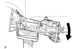
- Tilt the transmission downward.
- NOTICE:
- Make sure the cooling fan does not contact the fan shroud.
Disconnect the transmission connectors.
Disconnect the temperature sensor connector.
Disconnect the park/neutral position switch connector.
Disconnect the 2 speed sensor connectors.
Disconnect the transmission wire connector.
Disconnect the transfer connectors.
Disconnect the indicator switch connector (for 4WD).
Disconnect the speedometer sensor connector.
Disconnect the indicator switch connector (for L4).
Disconnect the indicator switch connector (neutral).
Detach the 8 wire harness clamps.
| 24.
REMOVE AUTOMATIC TRANSMISSION ASSEMBLY |
|
Remove the flywheel housing dust seal.
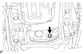
- Turn the crankshaft to gain access to each bolt.
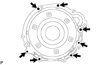
Hold the crankshaft pulley bolt with a wrench and remove the 6 torque converter clutch setting bolts.
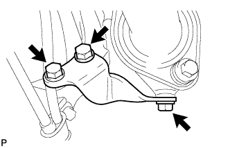
- Remove the 3 bolts and manifold stay.
- Remove the 7 bolts.
Separate the transmission from the engine.
| 25.
REMOVE TRANSFER ASSEMBLY |
|
Remove the transfer assembly (Click here).
| 26.
REMOVE TORQUE CONVERTER CLUTCH ASSEMBLY |
|
Remove the torque converter clutch from the automatic transmission assembly.
| 27.
REMOVE TRANSMISSION CONTROL CABLE BRACKET |
|
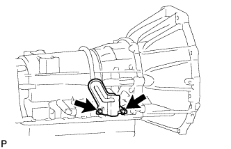
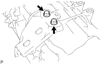
Remove the 2 bolts and control cable bracket from the transmission.