REMOVAL
Removal / installation · Vehicles built Jun 2011 – Jul 2012
Versions by build date: Jun 2011 – Jul 2012 Aug 2012 – Jul 2013 from Aug 2013
- HINT:
- A bolt without a torque specification is shown in the standard bolt chart (Click here).
| 1.
DISCONNECT CABLE FROM NEGATIVE BATTERY TERMINAL |
 |
- CAUTION:
- Wait at least 90 seconds after disconnecting the cable from the negative (-) battery terminal to prevent airbag and seat belt pretensioner activation.
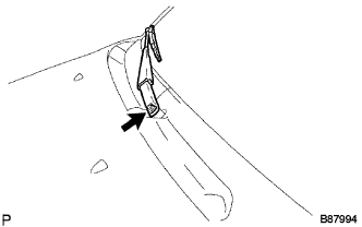
| 2.
REMOVE FRONT WIPER ARM HEAD CAP
|
|
Remove the 2 caps.
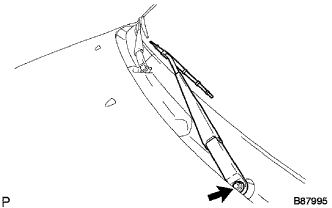
| 3.
REMOVE FRONT WIPER ARM AND BLADE ASSEMBLY LH
|
|
Remove the nut and arm & blade.
| 4.
REMOVE FRONT WIPER ARM AND BLADE ASSEMBLY RH
|
|
Remove the nut and arm & blade.
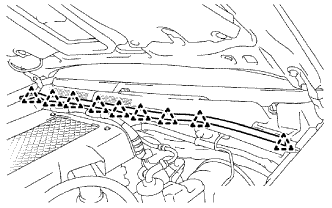
| 5.
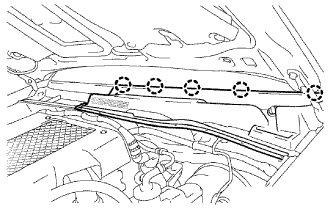
REMOVE HOOD TO COWL TOP SEAL
|
|
Detach the 9 clips and remove the seal.
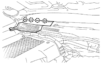
| 6.
REMOVE COWL TOP VENTILATOR LOUVER LH
|
|
Detach the 4 claws and remove the louver.
| 7.
REMOVE COWL TOP VENTILATOR LOUVER RH
|
|
Detach the 5 claws and remove the louver.
| 8.
REMOVE FRONT DOOR OPENING TRIM LH |
|
Partially remove the front door opening trim LH so that the front pillar garnish LH can be removed (Click here).
| 9.
REMOVE FRONT DOOR OPENING TRIM RH |
|
Partially remove the front door opening trim RH so that the front pillar garnish RH can be removed (Click here).
| 10.
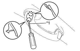
REMOVE FRONT NO. 1 ASSIST GRIP PLUG LH (w/ Assist Grip)
|
|
- HINT:
- Use the same procedure for both front No. 1 assist grip plugs.
Using a screwdriver, detach the 2 claws and remove the front No. 1 assist grip plug.
- HINT:
- Tape the screwdriver tip before use.
Text in Illustration
*1
|
Protective Tape
|
| 11.
REMOVE FRONT NO. 1 ASSIST GRIP PLUG RH (w/ Assist Grip)
|
|
- HINT:
- Use the same procedure described for the LH side.
| 12.
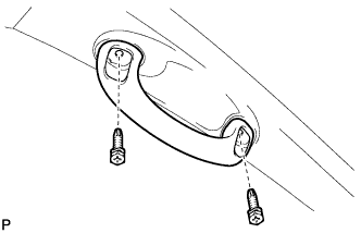
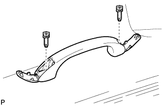
REMOVE FRONT ASSIST GRIP SUB-ASSEMBLY (w/ Assist Grip)
|
|
- HINT:
- Use the same procedure for both front assist grips.
Remove the 2 screws and front assist grip.
| 13.
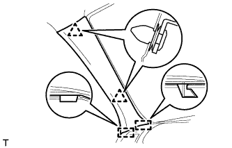
REMOVE FRONT PILLAR GARNISH LH
|
|
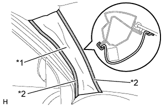
Detach the 2 clips and 2 guides and remove the front pillar garnish.
- w/ Curtain Shield Airbag:
Protect the curtain shield airbag assembly.
Thoroughly cover the airbag with a cloth or nylon sheet and fix the ends of the cover with adhesive tape, as shown in the illustration.
- NOTICE:
- Cover the curtain shield airbag with a protective cover as soon as the front pillar garnish is removed.
Text in Illustration
*1
|
Protective Cover
|
*2
|
Adhesive Tape
|
| 14.
REMOVE FRONT PILLAR GARNISH RH
|
|
- HINT:
- Use the same procedure described for the LH side.
| 15.
REMOVE VISOR ASSEMBLY LH
|
|
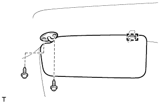
Detach the guide.
Remove the 2 screws and visor.
| 16.
REMOVE VISOR ASSEMBLY RH
|
|
- HINT:
- Use the same procedure described for the LH side.
| 17.
REMOVE VISOR HOLDER LH
|
|
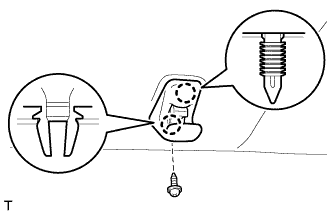
Remove the screw.
Detach the 2 claws and remove the visor holder.
| 18.
REMOVE VISOR HOLDER RH
|
|
- HINT:
- Use the same procedures described for the LH side.
| 19.
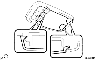
REMOVE ASSIST GRIP (w/ Assist Grip)
|
|
- HINT:
- Use the same procedure for all assist grips.
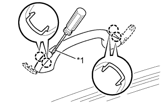
Using a screwdriver, detach the 4 claws and open the 2 covers.
- HINT:
- Tape the screwdriver tip before use.
Text in Illustration
*1
|
Protective Tape
|
- Remove the 2 screws and assist grip.
| 20.
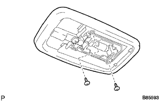
REMOVE NO. 1 ROOM LIGHT ASSEMBLY
|
|
- Using a screwdriver, detach the 4 claws and remove the lens.
- HINT:
- Tape the screwdriver tip before use.
- Remove the 2 screws and room light.
Disconnect the lamp connector.
| 21.
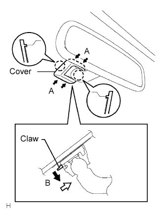
REMOVE INNER REAR VIEW MIRROR ASSEMBLY
|
|
Push the cover in the direction indicated by the arrows labeled A and remove it.
While holding down the claw in the direction of the black arrow labeled B, slide the mirror in the direction of the white arrow and remove it.
| 22.
REMOVE ROOF HEADLINING ASSEMBLY |
|
- HINT:
- It is not necessary to completely remove the roof headlining. Slightly lower the front section of the roof headlining.
For single cab (Click here)For extra cab (Click here)For double cab (Click here)
| 23.
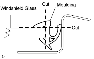
REMOVE WINDSHIELD MOULDING OUTER UPPER |
|
Using a knife, cut off the moulding as shown in the illustration.
- NOTICE:
- Be careful not to damage the vehicle body.
Remove the remaining moulding.
- HINT:
- Make a partial cut in the moulding. Then pull and remove it by hand.
| 24.
REMOVE WINDSHIELD GLASS |
|
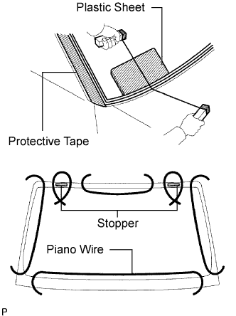
Apply protective tape to the outer surface of the vehicle body to prevent scratches.
From the interior, insert a piano wire between the vehicle body and glass as shown in the illustration.
Tie objects that can serve as handles (for example, wooden blocks) to all wire ends.
- NOTICE:
- When separating the glass from the vehicle, be careful not to damage the vehicle's paint or interior/exterior ornaments.
- To prevent the instrument panel from being scratched when removing the glass, place a plastic sheet between the piano wire and instrument panel.
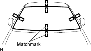
- Place matchmarks over the glass and vehicle body on the locations indicated in the illustration.
- HINT:
- Matchmarks do not need to be place if not reusing the glass.
Cut through the adhesive by pulling the piano wire around the glass.
- NOTICE:
- Leave as much adhesive on the vehicle body as possible when cutting through the adhesive.
Disengage the stoppers.
Using suction cups, remove the glass.
| 25.
CLEAN WINDSHIELD GLASS |
|
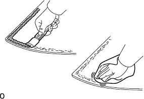
Using a scraper, remove the damaged stoppers, dams and adhesive sticking to the glass.
Clean the outer edges of the glass with non-residue solvent.
- NOTICE:
- Do not touch the glass surface after cleaning it.
- Even if using new glass, clean it with non-residue solvent.
| 26.
CLEAN VEHICLE BODY |
|
Clean and shape the contact surface of the vehicle body.
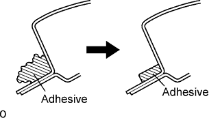
On the contact surface of the vehicle body, use a knife to cut away excess adhesive as shown in the illustration.
- HINT:
- Leave as much adhesive on the vehicle body as possible.
- NOTICE:
- Be careful not to damage the vehicle body.
Clean the contact surface of the vehicle body with cleaner.
- HINT:
- Even if all the adhesive has been removed, clean the vehicle body.