2014 Hilux · Service Manual ENGINE

REMOVAL

Removal / installation · Vehicles built Jun 2011 – Jul 2012

Versions by build date: Jun 2011 – Jul 2012 Aug 2012 – Jul 2013 from Aug 2013

NOTICE:
  1. When replacing the injectors (including shuffling the injectors between the cylinders), common rail or cylinder head, it is necessary to replace the injection pipes with new ones.
  2. When replacing the fuel supply pump, common rail, cylinder block, cylinder head, cylinder head gasket or timing gear case, it is necessary to replace the fuel inlet pipe with a new one.


1. REMOVE ENGINE ASSEMBLY
(Click here)

2. REMOVE NO. 1 TIMING BELT COVER

A015094E01
  1. Remove the bolt and water hose clamp.

  1. Remove the wire harness clamp.

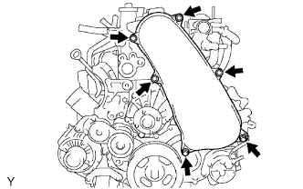
  1. Remove the 6 bolts and timing belt cover.


3. REMOVE TIMING BELT
(Click here)

4. REMOVE NO. 1 TIMING BELT TENSIONER ASSEMBLY

5. REMOVE NO. 2 IDLE PULLEY ASSEMBLY

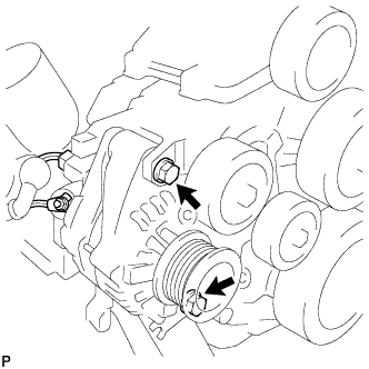
6. REMOVE GENERATOR ASSEMBLY

A111821
  1. Remove the nut and generator wire.

  1. Disconnect the generator connector.

  1. Remove the 2 bolts and generator.


7. REMOVE GENERATOR BRACKET
  1. Remove the bolt and generator bracket.


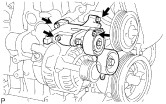
8. REMOVE V-RIBBED BELT TENSIONER ASSEMBLY

A098937E01
  1. Remove the 4 bolts and V-ribbed belt tensioner.


9. REMOVE NO. 1 COMPRESSOR MOUNTING BRACKET
  1. Remove the 4 bolts and No. 1 compressor mounting bracket.


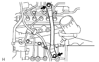
10. REMOVE MANIFOLD STAY

A099622E01
  1. Remove the 2 bolts and stay.


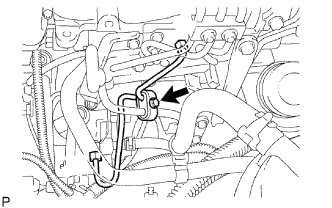
11. REMOVE FUEL INLET PIPE SUB-ASSEMBLY
  1. Remove the engine oil level dipstick.

  1. G036615E01
    Remove the bolt and clamp.

  1. Remove the bolt and engine oil level dipstick guide.

  1. Remove the O-ring engine oil level dipstick guide.

  1. A098969E03
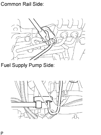
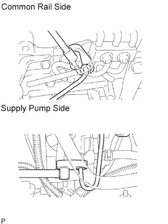
    Using a 17 mm union nut wrench, loosen the union nuts and remove the fuel inlet pipe.


12. REMOVE NO. 1, NO. 2 AND NO. 3 INJECTION PIPE SUB-ASSEMBLY

NOTICE:
  1. After removing the fuel pipe, cover the outlets on the common rail with tape to keep out foreign matter.
  2. After removing the fuel pipe, put it in a plastic bag to prevent foreign matter from contaminating its injector inlet.

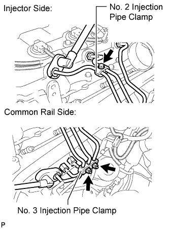
  1. A231803E01
    Remove the bolt and No. 2 injection pipe clamp.

  1. Remove the 2 nuts and No. 3 injection pipe clamp.

  1. Using a 17 mm union nut wrench, loosen the union nuts and remove the No. 1, No. 2 and No. 3 injection pipes.


13. REMOVE NO. 4 INJECTION PIPE SUB-ASSEMBLY

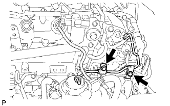
  1. A098893E01
    Remove the 2 bolts and disconnect the 2 injection pipe clamps.

    NOTICE:
    If an injection pipe clamp is removed from the No. 4 injection pipe, replace the injection clamp with a new one.

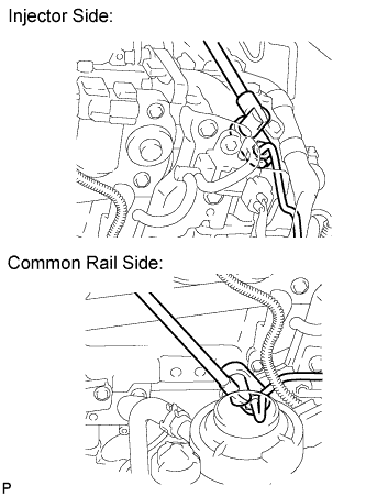
  1. A231804E01
    Using a 17 mm union nut wrench, loosen the union nuts and remove the No. 4 injection pipe.


14. REMOVE CYLINDER HEAD COVER SUB-ASSEMBLY

NOTICE:
If the cylinder head cover is removed, replace the 4 No. 3 cylinder head cover gaskets with new ones.

  1. A152277
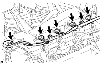
    Remove the 3 bolts and disconnect the 4 connectors.

  1. Disconnect the ventilation hose.

  1. A060180E01
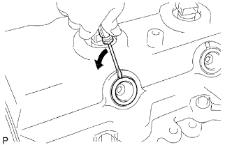
    Using a small screwdriver, remove the nozzle holder seal by prying the portion between the nozzle holder seal and the cutout part of the cylinder head cover.

  1. G034877E01
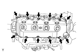
    Remove the 10 bolts, 2 nuts, cylinder head cover and cylinder head cover gasket.

  1. A289511
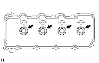
    Remove the 4 No. 3 cylinder head cover gaskets from the cylinder head cover.


15. REMOVE CAMSHAFT TIMING PULLEY

  1. A060182E01
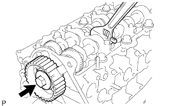
    Remove the bolt of the camshaft timing pulley by holding the camshaft with a wrench.

    NOTICE:
    Make sure to remove the bolt of the camshaft timing pulley with the timing belt not installed.

  1. Remove the camshaft timing pulley.


16. REMOVE NO. 1 TIMING BELT IDLER SUB-ASSEMBLY

17. REMOVE NO. 2 TIMING BELT COVER
  1. Remove the 4 bolts, nuts and No. 2 timing belt cover.


18. REMOVE WATER PUMP ASSEMBLY

A225339
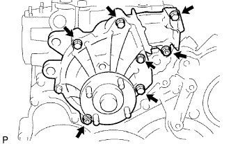
  1. Remove the 5 bolts, 2 nuts, water pump and gasket.


19. REMOVE VACUUM PUMP ASSEMBLY

  1. A098930E01
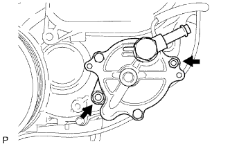
    Remove the 2 nuts, vacuum pump and 2 O-rings.


20. REMOVE VANE PUMP ASSEMBLY

  1. A233594
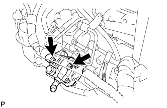
    Remove the 2 nuts, vane pump and O-ring.


21. REMOVE PUMP DRIVE SHAFT PULLEY

  1. A038747E01
    Remove the 4 bolts, No. 2 camshaft timing pulley flange and pump drive shaft pulley.

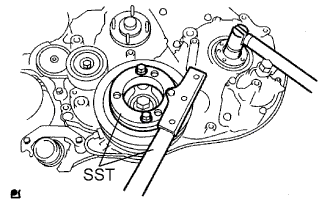
  1. A070711E01
    Using SST, hold the crankshaft pulley and remove the nut and O-ring.
    SST
    09213-58014  
    09330-00021  


22. REMOVE CRANKSHAFT PULLEY

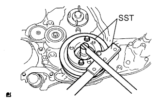
  1. A072413E02
    Using SST, remove the pulley bolt.
    SST
    09213-58014  
    09330-00021  

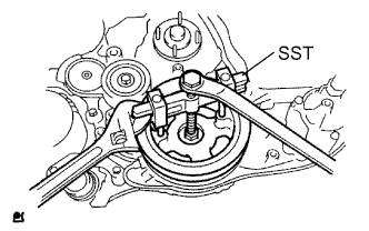
  1. A072414E02
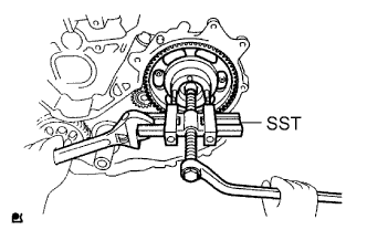
    Using SST, remove the pulley.
    SST
    09950-50013   (09951-05010, 09952-05010, 09953-05020, 09954-05021)

    NOTICE:
    Apply oil or grease to the threads and tip of SST (center bolt) before using it.


23. REMOVE CAMSHAFT POSITION SENSOR
  1. Remove the bolt and camshaft position sensor.


24. REMOVE CRANKSHAFT POSITION SENSOR
  1. Remove the bolt and crankshaft position sensor.


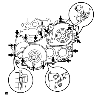
25. REMOVE TIMING GEAR COVER

A038748E01
  1. Remove the bolt and No. 1 vacuum transmitting pipe.

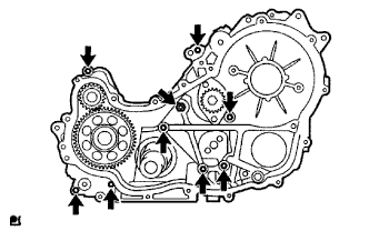
  1. Remove the 14 bolts and 2 nuts.

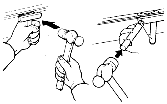
  1. Using a slotted screwdriver, gently separate the cover from the timing gear case.

    HINT:
    There are tiny slots that allow you to insert the slotted screwdriver tip for separating the timing gear case and its cover. Refer to the illustration for the slot locations.

    NOTICE:
    Be careful not to damage the contact surfaces of the timing gear case and its cover.

  1. Remove the cover and O-ring.


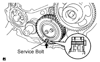
26. FIX NO. 1 IDLE GEAR

A038749E01
  1. Fix the sub idle gear to the idle gear with a service bolt.

    Torque:
    8.0 N*m{ 82 kgf*cm , 71 in.*lbf }

    NOTICE:
    If the bolt hole of the sub idle gear is not aligned with the bolt hole of the idle gear, rotate the crankshaft counterclockwise to align the bolt holes. Then install the service bolt.

    HINT:
    The service bolt is installed to eliminate torsional force caused by the idle gear springs, which are located between the idle gear and sub idle gear. Torsional force will cause the sub idle gear's tooth and idle gear's tooth to be out of alignment.

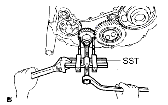
27. REMOVE CRANKSHAFT TIMING GEAR
  1. Remove the No. 1 crankshaft sensor plate.

  1. Install a service bolt to the crankshaft.

  1. A071161E01
    Using SST, remove the crankshaft timing gear.
    SST
    09950-50013   (09951-05010, 09952-05010, 09953-05020, 09954-05010)


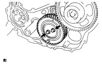
28. REMOVE NO. 1 IDLE GEAR

A038751E01
  1. Remove the 2 bolts and idle gear thrust plate, and then remove the idle gear together with the sub idle gear.

  1. Remove the No. 1 idle gear shaft.


29. REMOVE INJECTION GEAR

A071164E01
  1. Using SST, remove the injection gear.

    SST
    09950-50013   (09951-05010, 09952-05010, 09953-05020, 09954-05021)


30. REMOVE FUEL SUPPLY PUMP ASSEMBLY

G036615E01
  1. Remove the bolt and clamp.

  1. Remove the 2 bolts and oil level gauge guide.

  1. A098969E05
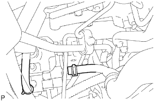
    Using a 17 mm union nut wrench, loosen the union nuts and remove the fuel inlet pipe.

  1. A098895E01
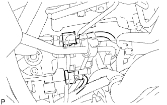
    Disconnect the 2 fuel hoses.

  1. A098896E01
    Disconnect the 2 connectors.

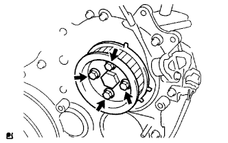
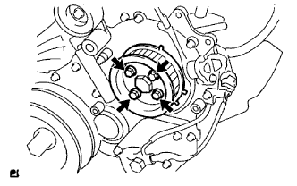
  1. A070710E01
    Remove the 4 bolts indicated by the arrows in the illustration.

  1. Remove the No. 2 camshaft timing pulley flange and pump drive shaft pulley.

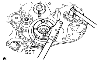
  1. A070711E02
    Remove the set nut and O-ring while holding the crankshaft pulley by using SST.
    SST
    09213-58013  
    09330-00021  

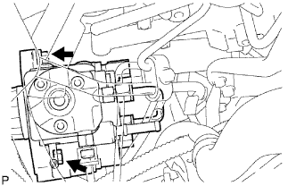
  1. A098897E01
    Loosen the 2 nuts.

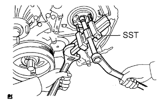
  1. A070714E01
    Using SST, disconnect the pump from the injection gear.
    SST
    09950-50013   (09951-05010, 09952-05010, 09953-05020, 09954-05021)

    NOTICE:
    Apply lubricant to the threads and tip of SST (center bolt) before using it.

  1. Remove the 2 nuts and pump.

    NOTICE:
    1. Do not hold the pump or carry it holding the pipe.
    2. The pump must be kept horizontal.

  1. Remove the O-ring.


31. REMOVE OIL PAN SUB-ASSEMBLY
  1. Remove the 22 bolts and 2 nuts.

  1. Z004119E03
    Insert the blade of an oil pan seal cutter between the cylinder block and oil pan. Cut through the applied sealer and remove the oil pan.

    NOTICE:
    1. Do not use the oil pan seal cutter for the timing gear case and rear oil seal retainer.
    2. Be careful not to damage the oil pan flange.


32. REMOVE OIL STRAINER SUB-ASSEMBLY
  1. Remove the 2 bolts, nut, oil strainer and gasket.


33. REMOVE TIMING GEAR CASE ASSEMBLY

A038755E01
  1. Remove the 8 bolts and union bolt. Then remove the timing gear case, 2 O-rings and gasket.

    NOTICE:
    Do not drop the oil pump rotor.

← COMPONENTS (from Jun 2011)REMOVAL (Aug 2012 – Jul 2013) →