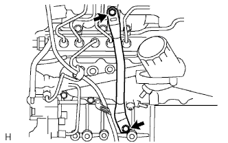
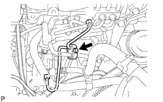
When replacing the injectors (including shuffling the injectors between the cylinders), common rail or cylinder head, it is necessary to replace the injection pipes with new ones.
When replacing the fuel supply pump, common rail, cylinder block, cylinder head, cylinder head gasket or timing gear case, it is necessary to replace the fuel inlet pipe with a new one.
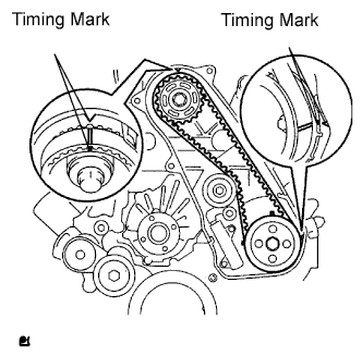
Turn the crankshaft clockwise and align the timing marks as shown in the illustration.
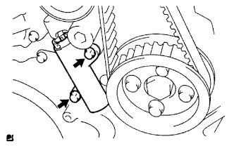
Uniformly loosen the 2 bolts and remove the timing belt tensioner.
Remove the timing belt.
Using a 10 mm hexagon wrench, remove the bolt, timing belt idler and washer.
HINT:
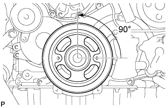
When turning the camshaft while the timing belt is removed, turn the crankshaft 90° counterclockwise.
When installing the timing belt, return the camshaft to the timing marks and then turn the crankshaft clockwise until it aligns with the timing marks, as shown in the illustration.
4.
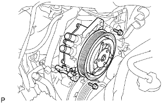
REMOVE VISCOUS WITH MAGNET CLUTCH HEATER ASSEMBLY
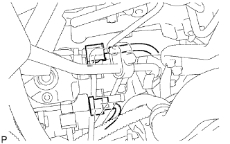
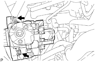
Disconnect the connector.
Remove the 2 bolts and viscous with magnet clutch heater assembly.
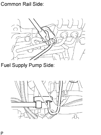
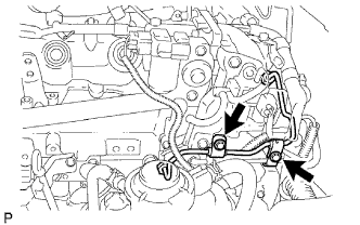
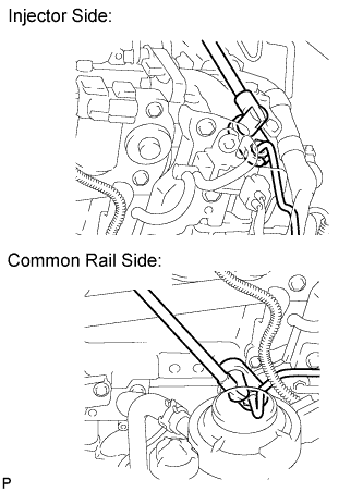
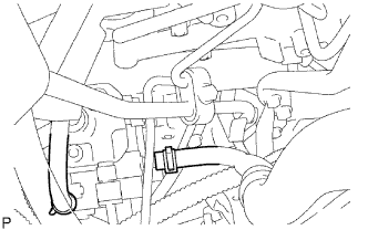
After removing the fuel pipe, cover the outlets on the common rail with tape to keep out foreign matter.
After removing the fuel pipe, put it in a plastic bag to prevent foreign matter from contaminating its injector inlet.
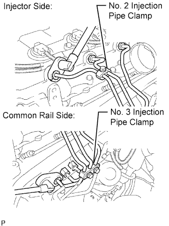
Remove the bolt and No. 2 injection pipe clamp.
Remove the 2 nuts and No. 3 injection pipe clamp.
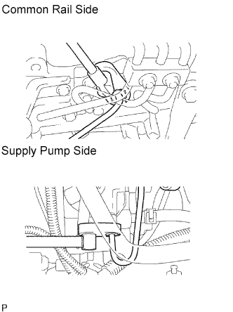
Using a 17 mm union nut wrench, loosen the union nuts and remove the No. 1, No. 2 and No. 3 injection pipes.
14.
REMOVE NO. 4 INJECTION PIPE SUB-ASSEMBLY
Remove the 2 bolts.
NOTICE:
If an injection pipe clamp is removed from the No. 4 injection pipe, replace the injection clamp with a new one.
Using a 17 mm union nut wrench, loosen the union nuts and remove the No. 4 injection pipe.
15.
REMOVE CYLINDER HEAD COVER SUB-ASSEMBLY
NOTICE:
If the cylinder head cover is removed, replace the 4 No. 3 cylinder head cover gaskets with new ones.
Disconnect the ventilation hose.
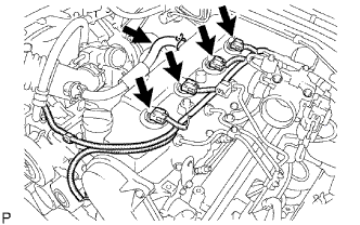
Disconnect the 4 injector connectors.
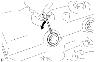
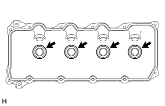
Using a small screwdriver, remove the 4 nozzle holder seals by prying the portion between each nozzle holder seal and the cutout part of the cylinder head cover.
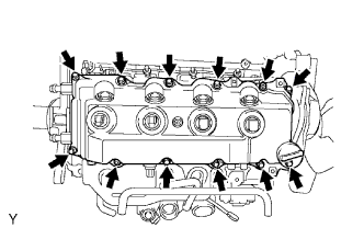
Remove the 10 bolts, 2 nuts, cylinder head cover and gasket.
Remove the 4 No. 3 cylinder head cover gaskets from the cylinder head cover.
16.
REMOVE CAMSHAFT TIMING PULLEY
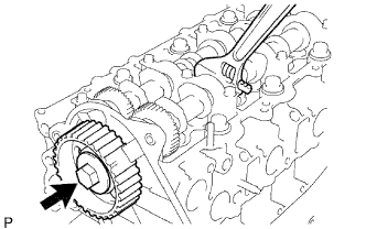
Remove the bolt of the camshaft timing pulley by holding the camshaft with a wrench.
NOTICE:
Make sure to remove the bolt of the camshaft timing pulley with the timing belt not installed.
Remove the camshaft timing pulley.
17.
REMOVE NO. 1 TIMING BELT IDLER SUB-ASSEMBLY
18.
REMOVE NO. 2 TIMING BELT COVER
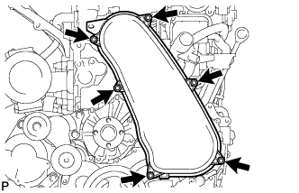
Remove the 4 bolts, nut and timing belt cover.
19.
REMOVE WATER PUMP ASSEMBLY
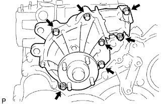
Remove the 5 bolts, 2 nuts, water pump and gasket.
20.
REMOVE VACUUM PUMP ASSEMBLY
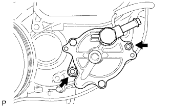
Remove the 2 nuts, vacuum pump and 2 O-rings.
21.
REMOVE VANE PUMP ASSEMBLY
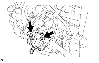
Remove the 2 nuts, vane pump and O-ring.
22.
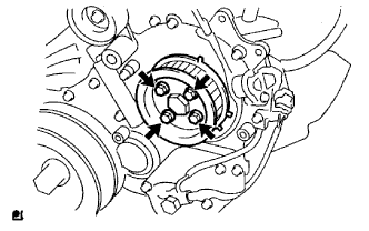
REMOVE PUMP DRIVE SHAFT PULLEY
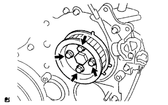
Remove the 4 bolts, No. 2 camshaft timing pulley flange and pump drive shaft pulley.
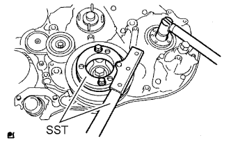
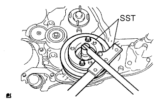
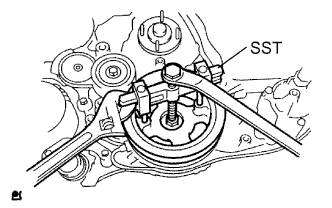
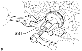
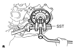
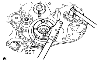
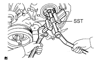
Using SST, hold the crankshaft pulley and remove the nut and O-ring.
Apply oil or grease to the threads and tip of SST (center bolt) before using it.
24.
REMOVE CAMSHAFT POSITION SENSOR
Remove the bolt and camshaft position sensor.
25.
REMOVE CRANKSHAFT POSITION SENSOR
Remove the bolt and crankshaft position sensor.
26.
REMOVE TIMING GEAR COVER
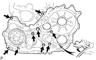
Remove the wire harness clamp.
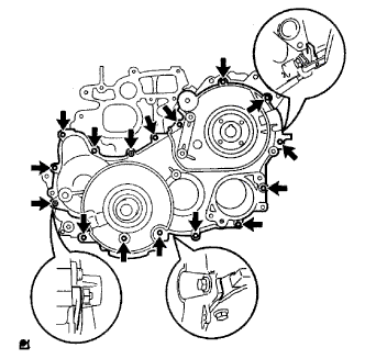
Remove the 14 bolts and 2 nuts.
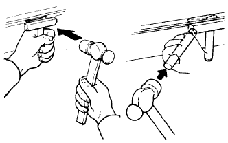
Using a slotted screwdriver, gently separate the cover from the timing gear case.
HINT:
There are tiny slots that allow you to insert the slotted screwdriver tip for separating the timing gear case and its cover. Refer to the illustration for the slot locations.
NOTICE:
Be careful not to damage the contact surfaces of the timing gear case and its cover.
Remove the cover and O-ring.
27.
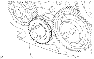
REMOVE NO. 1 IDLE GEAR
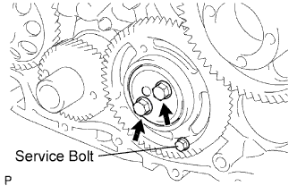
Secure the No. 2 idle sub gear to the No. 1 idle gear with a service bolt.
Torque:
8.0 N*m{
82 kgf*cm
, 71 in.*lbf
}
NOTICE:
If the bolt hole of the No. 2 idle sub gear is not aligned with the bolt hole of the No. 1 idle gear, rotate the crankshaft counterclockwise to align the bolt holes. Then install the service bolt.
Remove the 2 bolts and thrust plate.
Remove the service bolt.
Turn the No. 2 idle sub gear and align the gear teeth of the No. 1 idle gear and No. 2 idle sub gear.
Remove the No. 1 idle gear together with the No. 2 idle sub gear.