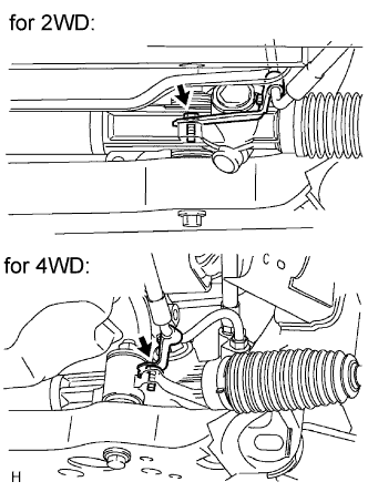
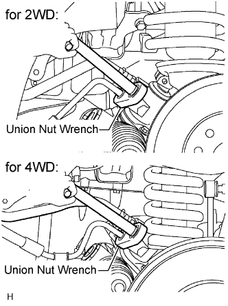
Align the matchmarks on the steering intermediate shaft and steering link.
Install the bolt.
Torque:
35 N*m{
357 kgf*cm
, 26 ft.*lbf
}
10.
CONNECT STEERING SLIDING YOKE
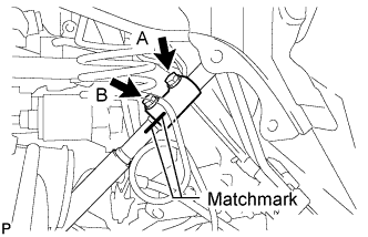
Align the matchmarks on the steering sliding yoke and steering intermediate shaft, and connect the steering sliding yoke to the steering intermediate shaft.
Install the bolt labeled B.
Torque:
35 N*m{
357 kgf*cm
, 26 ft.*lbf
}
Tighten the bolt labeled A.
Torque:
35 N*m{
357 kgf*cm
, 26 ft.*lbf
}
11.
CONNECT TIE ROD END SUB-ASSEMBLY LH
Connect the tie rod end to the steering knuckle arm with the nut.
Torque:
49 N*m{
500 kgf*cm
, 36 ft.*lbf
}
for 2WD
91 N*m{
928 kgf*cm
, 67 ft.*lbf
}
for 4WD
Install the cotter pin.
12.
CONNECT TIE ROD END SUB-ASSEMBLY RH
HINT:
Use the same procedures described for the LH side.
13.
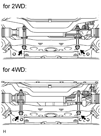
INSTALL FRONT SIDE MEMBER TO FRONT SUSPENSION CROSSMEMBER BRACE
Install the crossmember brace with the 8 bolts.
Torque:
50 N*m{
510 kgf*cm
, 37 ft.*lbf
}
14.
INSTALL NO. 1 ENGINE UNDER COVER (for 4WD)
Install the under cover with the 4 bolts.
Torque:
28 N*m{
286 kgf*cm
, 21 ft.*lbf
}
15.
INSTALL NO. 2 ENGINE UNDER COVER (for 4WD)
Install the under cover with the 4 bolts.
Torque:
28 N*m{
286 kgf*cm
, 21 ft.*lbf
}
16.
INSTALL FRONT WHEEL
17.
PLACE FRONT WHEELS FACING STRAIGHT AHEAD
18.
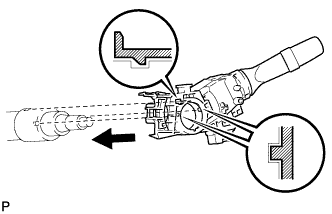
INSTALL WINDSHIELD WIPER SWITCH ASSEMBLY
Attach the claw to install the windshield washer switch.
NOTICE:
Do not push the claw with excessive force as damage may occur.
Connect the connectors.
19.
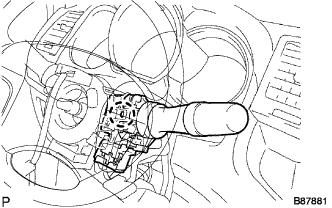
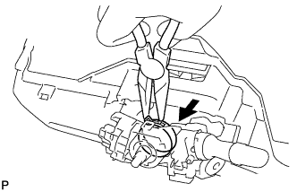
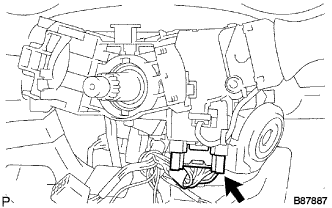
INSTALL HEADLIGHT DIMMER SWITCH ASSEMBLY
Install the headlight dimmer switch with the claw as shown in the illustration.
Install the headlight dimmer switch with the clamp.
Connect the connector.
20.
INSTALL SPIRAL CABLE SUB-ASSEMBLY
21.
INSTALL STEERING COLUMN UPPER COVER
22.
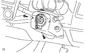
INSTALL STEERING COLUMN LOWER COVER
Install the cover lower with the 3 screws.
23.
ADJUST SPIRAL CABLE
24.
INSTALL STEERING WHEEL ASSEMBLY
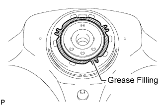
for 3 spoke: Apply the silicon grease to the steering wheel.
Align the matchmarks on the steering wheel and main shaft.