2014 Hilux · Service Manual STEERING

INSTALLATION

Removal / installation · Vehicles built Aug 2012 – Jul 2013

Versions by build date: Jun 2011 – Oct 2011 Nov 2011 – Mar 2012 Apr 2012 – Jul 2012 Aug 2012 – Jul 2013 from Aug 2013


1. INSTALL TIE ROD END SUB-ASSEMBLY LH
  1. Screw the lock nut and tie rod end onto the rack end until the matchmarks are aligned.

  1. After adjusting toe-in, torque the nut.

    Torque:
    56 N*m{ 556 kgf*cm , 41 ft.*lbf }


2. INSTALL TIE ROD END SUB-ASSEMBLY RH

HINT:
Use the same procedures described for the LH side.


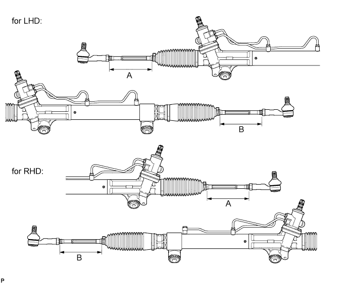
3. INSPECT AND ADJUST TIE ROD END SUB-ASSEMBLY (w/ VSC)

  1. Adjust the tie rod end LH and RH so that distance A and B are within the specified ranges.

    C226929E01

    Standard Length:

    Dimension
    Control range (for 4WD)
    Control range (for 2WD)
    for LHD
    A
    153.7 to 155.7 mm (6.06 to 6.12 in.)
    155.5 to 157.5 mm (6.13 to 6.20 in.)
    B
    for RHD
    A
    153.7 to 155.7 mm (6.06 to 6.12 in.)
    155.5 to 157.5 mm (6.13 to 6.20 in.)
    B

    HINT:
    1. The values listed above are reference values.
    2. The toe-in is adjusted in a step.


4. INSTALL POWER STEERING LINK ASSEMBLY

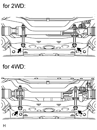
  1. G039377E03
    Install the steering link with the 2 bolts and 2 nuts.

    Torque:
    95 N*m{ 969 kgf*cm , 70 ft.*lbf }

    HINT:
    for 4WD:
    If necessary, return the differential to its original position and install the differential mount.


5. INSTALL FRONT STABILIZER BAR
(Click here)

6. STABILIZE SUSPENSION

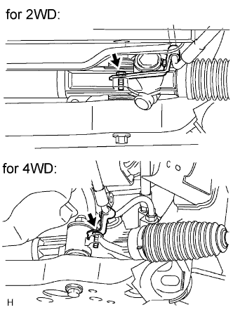
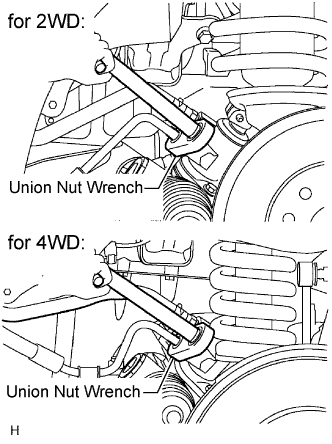
7. CONNECT STEERING GEAR OUTLET RETURN TUBE

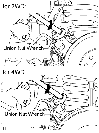
  1. G039375E06
    Using a union nut wrench, connect the outlet return tube.

    Torque:
    44 N*m{ 449 kgf*cm , 33 ft.*lbf }

    NOTICE:
    Use the formula to calculate special torque values for situations where a union nut wrench is combined with a torque wrench (Click here).

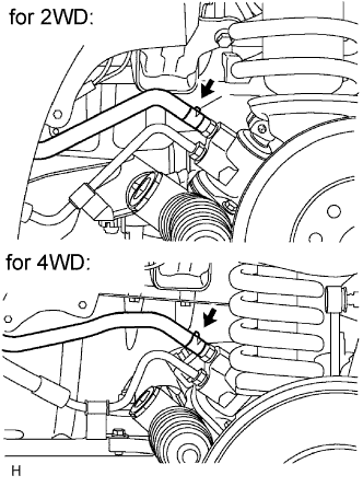
  1. G039376E04
    Install the hose with the clip.


8. CONNECT PRESSURE FEED TUBE ASSEMBLY

  1. G038597E02
    Install the pressure feed tube to the steering link with the bolt.

    Torque:
    28 N*m{ 286 kgf*cm , 21 ft.*lbf }

  1. G039370E03
    Using a union nut wrench, tighten the flare nut and connect the pressure feed tube.

    Torque:
    44 N*m{ 449 kgf*cm , 33 ft.*lbf }

    NOTICE:
    Use the formula to calculate special torque values for situations where a union nut wrench is combined with a torque wrench (Click here).


9. CONNECT NO. 2 STEERING INTERMEDIATE SHAFT SUB-ASSEMBLY
  1. Align the matchmarks on the steering intermediate shaft and steering link.

  1. Install the bolt.

    Torque:
    35 N*m{ 357 kgf*cm , 26 ft.*lbf }


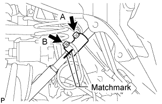
10. CONNECT STEERING SLIDING YOKE

  1. C239647E02
    Align the matchmarks on the steering sliding yoke and steering intermediate shaft, and connect the steering sliding yoke to the steering intermediate shaft.

  1. Install the bolt labeled B.

    Torque:
    35 N*m{ 357 kgf*cm , 26 ft.*lbf }

  1. Tighten the bolt labeled A.

    Torque:
    35 N*m{ 357 kgf*cm , 26 ft.*lbf }


11. CONNECT TIE ROD END SUB-ASSEMBLY LH
  1. Connect the tie rod end to the steering knuckle arm with the nut.

    Torque:
    49 N*m{ 500 kgf*cm , 36 ft.*lbf } for 2WD
    91 N*m{ 928 kgf*cm , 67 ft.*lbf } for 4WD

  1. Install the cotter pin.


12. CONNECT TIE ROD END SUB-ASSEMBLY RH

HINT:
Use the same procedures described for the LH side.


13. INSTALL FRONT SIDE MEMBER TO FRONT SUSPENSION CROSSMEMBER BRACE
  1. Install the crossmember brace with the 8 bolts.

    Torque:
    50 N*m{ 510 kgf*cm , 37 ft.*lbf }


14. INSTALL NO. 1 ENGINE UNDER COVER (for 4WD)
  1. Install the under cover with the 4 bolts.

    Torque:
    28 N*m{ 286 kgf*cm , 21 ft.*lbf }


15. INSTALL NO. 2 ENGINE UNDER COVER (for 4WD)
  1. Install the under cover with the 4 bolts.

    Torque:
    28 N*m{ 286 kgf*cm , 21 ft.*lbf }


16. INSTALL FRONT WHEEL

17. PLACE FRONT WHEELS FACING STRAIGHT AHEAD

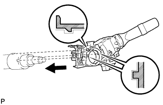
18. INSTALL WINDSHIELD WIPER SWITCH ASSEMBLY

  1. E225945
    Attach the claw to install the windshield washer switch.

    NOTICE:
    Do not push the claw with excessive force as damage may occur.

  1. Connect the connectors.


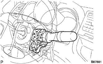
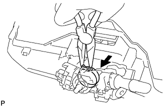
19. INSTALL HEADLIGHT DIMMER SWITCH ASSEMBLY

  1. B113204
    Install the headlight dimmer switch with the claw as shown in the illustration.

  1. B113203
    Install the headlight dimmer switch with the clamp.

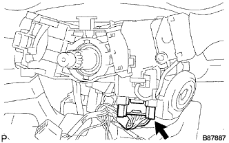
  1. B087887
    Connect the connector.


20. INSTALL SPIRAL CABLE SUB-ASSEMBLY

21. INSTALL STEERING COLUMN UPPER COVER

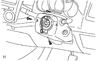
22. INSTALL STEERING COLUMN LOWER COVER

G034336E01
  1. Install the cover lower with the 3 screws.


23. ADJUST SPIRAL CABLE

24. INSTALL STEERING WHEEL ASSEMBLY

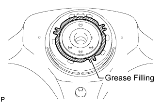
  1. C238264E02
    for 3 spoke:
    Apply the silicon grease to the steering wheel.

  1. Align the matchmarks on the steering wheel and main shaft.

  1. Install the steering set nut.

    Torque:
    50 N*m{ 510 kgf*cm , 37 ft.*lbf }


25. INSPECT STEERING WHEEL CENTER POINT

26. INSTALL STEERING PAD ASSEMBLY
(Click here)

27. CONNECT CABLE TO NEGATIVE BATTERY TERMINAL

28. PERFORM INITIALIZATION
  1. Perform initialization (Click here).

    NOTICE:
    Certain systems need to be initialized after disconnecting and reconnecting the cable from the negative (-) battery terminal.


29. INSPECT SRS WARNING LIGHT
(Click here)

30. ADD POWER STEERING FLUID
(Click here)

31. BLEED AIR FROM POWER STEERING SYSTEM

32. CHECK FOR POWER STEERING FLUID LEAKAGE

33. INSPECT AND ADJUST FRONT WHEEL ALIGNMENT
(Click here)
← INSTALLATION (Apr 2012 – Jul 2012)INSTALLATION (from Aug 2013) →