Circuit diagnosis · Vehicles built Jun 2011 – Jul 2012
Versions by build date: Jun 2011 – Jul 2012from Aug 2012
DESCRIPTION
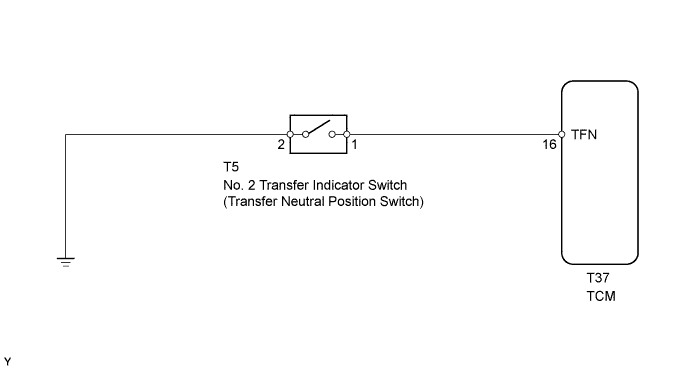
The propeller shaft and wheels are free even when the transmission shift lever is on P, as long as the transfer shift lever is on N. The A/T P indicator illuminates to warn the driver that the propeller shaft and wheels are not locked. If the A/T P indicator illuminates, the transfer shift lever should be moved from N.
WIRING DIAGRAM
INSPECTION PROCEDURE
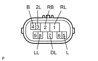
1. INSPECT PARK/NEUTRAL POSITION SWITCH
Disconnect the N1 park/neutral position switch connector.
Measure the resistance of the park/neutral position switch when the shift lever is moved to each position.
Standard resistance:
Tester Connection
Shift Lever Position
Specified Condition
4 (B) - 5 (L)
P or N
Below 1 Ω
4 (B) - 5 (L)
Not on P or N
10 kΩ or higher
1 (RL) - 2 (RB)
R
Below 1 Ω
1 (RL) - 2 (RB)
Not on R
10 kΩ or higher
2 (RB) - 7 (DL)
D
Below 1 Ω
2 (RB) - 7 (DL)
Not on D
10 kΩ or higher
2 (RB) - 3 (2L)
2
Below 1 Ω
2 (RB) - 3 (2L)
Not on 2
10 kΩ or higher
2 (RB) - 8 (LL)
L
Below 1 Ω
2 (RB) - 8 (LL)
Not on L
10 kΩ or higher
NG
REPLACE PARK/NEUTRAL POSITION SWITCH
OK
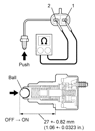
2. INSPECT NO. 2 TRANSFER INDICATOR SWITCH (TRANSFER NEUTRAL POSITION SWITCH)
Remove the transfer indicator switch.
Measure the resistance of the switch when pushing the ball at the tip of the switch.
Standard resistance:
Tester Connection
Switch Condition
Specified Condition
1 - 2
Not pushed
10 kΩ or higher
1 - 2
Pushed
Below 1 Ω
NG
REPLACE NO. 2 TRANSFER INDICATOR SWITCH (TRANSFER NEUTRAL POSITION SWITCH)
OK
3. INSPECT COMBINATION METER
Check the A/T P indicator light.
Disconnect the T5 switch connector.
Turn the ignition switch ON.
Connect the T5-1 terminal of the wire harness side connector to the body ground, and then check the A/T P indicator light.