DESCRIPTION
- HINT:
- For more information on the injector and the common rail system (Click here).
- If DTC P1238 is present, refer to the "Diagnostic Trouble Code (DTC) Table for Common Rail System" (Click here).
The ECM detects combustion deterioration for a specific cylinder.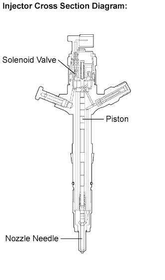

- HINT:
- The cylinder, which has the compensation value for Injection Feedback Val #1, #2, #3 and #4 that varies from other cylinders, may be malfunctioning.
- If DTC P0093 (fuel leaks from high-pressure area) is set simultaneously, a leakage malfunction of the cylinder has probably occurred.
- If DTC P0200 (open or short in the EDU or injector circuit) is set simultaneously, there is probably a faulty circuit located between the ECM and the injector including the EDU.
- If only DTC P1238 (injector malfunction) is present, an injector mechanical malfunction or insufficient compression (valve clearance etc.) has probably occurred. An open or short malfunction of the ECM, EDU or injector circuit is unlikely.
- The solenoid valve of the injector is the same type as that of the pressure discharge valve.
DTC No.
|
DTC Detection Condition
|
Main Trouble Area
|
Related Trouble Area
|
P1238
|
Engine speed fluctuation is large when idling (2 trip detection logic)
|
- Injector
- EDU (P0200 is set simultaneously)
- Open or short in engine wire harness (P0200 is set simultaneously)
- Connector connection (P0200 is set simultaneously)
- Compression pressure
- Valve clearance
|
- Valve timing
- Low quality fuel (fuel with low cetane number used)
- ECM
|
- HINT:
- After confirming DTC P1238, check the internal fuel pressure in Powertrain / Engine / Data List / Fuel Press using the intelligent tester.
- Reference:
Engine Speed
|
Fuel Pressure
|
Idling
|
Approximately 25000 to 35000 kPa
|
3,000 rpm (No engine load)
|
Approximately 50000 to 70000 kPa
|
MONITOR DESCRIPTION
- P1238 (Injection malfunction, except open or short in injector circuit):
This DTC will be set if the engine speed fluctuation between each cylinder is large. The ECM monitors changes in the crankshaft rotation speed using the crankshaft position sensor in order to detect improper combustion. The camshaft position sensor also plays a role in determining which cylinder has the problem. The fluctuation counter increases when irregular crankshaft rotation speed variation exceeds the threshold with the engine idling. Therefore, if any one of the cylinders is operating poorly (rough idle), the ECM sets this DTC.
MONITOR STRATEGY
Required Sensors
|
Crankshaft position sensor
|
Frequency of operation
|
Continuous
|
Duration
|
10 minutes
|
MIL Operation
|
2 driving cycles
|
TYPICAL ENABLING CONDITIONS
Item
|
Specification
|
Minimum
|
Maximum
|
Engine
|
At idling
|
Engine speed
|
750 rpm
|
-
|
Engine coolant temperature
|
20°C (68°F)
|
-
|
TYPICAL MALFUNCTION THRESHOLDS
Threshold
|
The number of irregular changes in the crankshaft rotation speed.
|
- HINT:
- The number of irregular changes in the crankshaft rotation speed indicates the insufficient combustion.
WIRING DIAGRAM
Refer to DTC P0200 (Click here).INSPECTION PROCEDURE
- NOTICE:
- After replacing the ECM, the new ECM needs registration (Click here) and initialization (Click here).
- HINT:
- If DTCs other than P1238 are present simultaneously, first perform troubleshoot those DTCs.
- Read freeze frame data using the intelligent tester. Freeze frame data records the engine condition when malfunctions are detected. When troubleshooting, freeze frame data can help determine if the vehicle was moving or stationary, if the engine was warmed up or not, and other data from the time the malfunction occurred.
| 1. CHECK OTHER DTC OUTPUT (IN ADDITION TO DTC P1238) |
 |
Connect the intelligent tester to the DLC3.
Turn the ignition switch ON and turn the tester ON.
Enter the following menus: Powertrain / Engine / DTC.
Read DTCs.
- Result:
Display (DTC output)
|
Proceed to
|
P1238
|
A
|
P1238 and other DTCs
|
B
|
- HINT:
- If codes other than P1238 are output, perform troubleshooting for those DTCs first.
|
B |
 |
|
|
|
| A |
|
 |
|
| 2. CHECK HARNESS AND CONNECTOR (ENGINE WIRE HARNESS) |
|
Check the wire harness and connector connections.
- OK:
- The wire harness and connectors have been connected securely and there are good connections
|
NG |
|
|
| REPAIR OR REPLACE HARNESS OR CONNECTOR |
|
|
| OK |
|
|
|
| 3. READ VALUE USING INTELLIGENT TESTER (COMPENSATION OF INJECTION VOLUME BETWEEN CYLINDERS) |
|
Connect the intelligent tester to the DLC3.
Turn the ignition switch ON and turn the tester ON.
Enter the following menus: Powertrain / Engine / Data List / Injection Feedback Val #1, #2, #3 and #4.
Read the value.
- Standard:
- The compensatory injection volume is between -4.9 mm3/st and 4.9 mm3/st
- HINT:
- If the injection is malfunctioning, the compensatory injection volume remains at -5.0 mm3/st or 5.0 mm3/st.
- The compensatory injection volume is usually between -3.0 mm3/st and 3.0 mm3/st.
Any cylinders that have a higher compensatory injection volume than shown above are considered to be faulty. Use the following steps to inspect and repair the cylinders.
- Result:
Result
|
Proceed to
|
Faulty cylinder is not identified
|
A
|
Faulty cylinder is identified
|
B
|
|
B |
 |
|
|
|
| A |
|
|
|
| 4. PERFORM ACTIVE TEST USING INTELLIGENT TESTER (INJECTION CUT FOR IDENTIFYING MALFUNCTION CYLINDER) |
|
Connect the intelligent tester to the DLC3.
Start the engine and turn the tester ON.
Enter the following menus: Powertrain / Engine / Active Test / Control the Cylinder #1 to #4 Fuel Cut.
Check the four cylinders in sequence to identify a faulty cylinder by performing the power-balance inspection.
- HINT:
- If the engine idle does not change when an injector is disabled, the cylinder being tested is malfunctioning.
| NEXT |
|
|
|
| 5. CHECK CYLINDER COMPRESSION PRESSURE OF MALFUNCTIONING CYLINDER |
|
Check the cylinder compression pressure.
- Standard:
- 2,700 kPa (27.5 kgf/cm2, 391 psi)
- Minimum pressure:
- 2,200 kPa (22.5 kgf/cm2, 320 psi)
- Difference between each cylinder:
- 500 kPa (5.0 kgf/cm2, 71 psi)
|
NG |
|
|
| CHECK ENGINE TO DETERMINE CAUSE OF LOW COMPRESSION |
|
|
| OK |
|
|
|
| 6. CHECK VALVE CLEARANCE OF MALFUNCTIONING CYLINDER |
|
- OK:
- The valve clearance is within the standard range
|
NG |
|
|
|
|
| NG |
|
|
|
| 7. CHECK IF DTC OUTPUT RECURS (DTC P1238) |
|
- HINT:
- After clearing the DTC, let the engine idle for 10 minutes after warming up, and then confirm that P1238 is not present again.
- OK:
- No DTC output
|
OK |
|
|
|
|
| NG |
|
|
|
| 8. REPLACE INJECTOR ASSEMBLY |
|
Replace injector assembly (Click here).
| NEXT |
|
|
|
| 9. CHECK IF DTC OUTPUT RECURS (DTC P1238) |
|
- HINT:
- After clearing the DTC, let the engine idle for 10 minutes after warming up, and then confirm that DTC P1238 is not present again.
| NEXT |
|
 |
|
|