2TR-FE ENGINE MECHANICAL CAMSHAFT INSTALLATION
PROCEDURE

 1.INSTALL CAMSHAFT TIMING GEAR ASSEMBLY
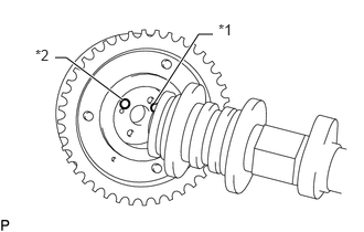
| *1 | Straight Pin |
| *2 | Pin Hole |
Align the pin hole and straight pin and install the camshaft timing gear to the camshaft.
Lightly press the gear against the camshaft and turn the gear. Push further at the position where the pin enters the groove.
- HINT:
-
Make sure that there is no gap between the flange of the gear and the camshaft.
With the camshaft timing gear fixed in place, install the flange bolt.
- Torque:
- 78 N*m (795 kgf*cm, 58 ft.*lbf)
Check that the camshaft timing gear can move in the retard direction and becomes locked at the most retarded position.
2.INSTALL VALVE LASH ADJUSTER ASSEMBLY
Inspect each valve lash adjuster before installing it (See page Engine / Hybrid System>2TR-FE ENGINE MECHANICAL>ENGINE UNIT>INSPECTION).
Install the 16 valve lash adjusters to the cylinder head.
- NOTICE:
-
Install each lash adjuster to the same place it was removed from.
3.INSTALL NO. 1 VALVE ROCKER ARM SUB-ASSEMBLY
Apply clean engine oil to the valve lash adjuster tips and valve stem cap surfaces.
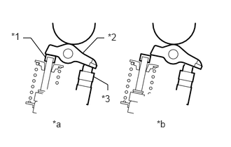
| *1 | Valve Stem Cap |
| *2 | Valve Rocker Arm |
| *3 | Valve Lash Adjuster |
| *a | CORRECT |
| *b | INCORRECT |
Install the 16 valve rocker arms as shown in the illustration.
- NOTICE:
-
Install the valve stem cap, lash adjuster and valve rocker arm to the same places they were removed from.
4.INSTALL CAMSHAFT
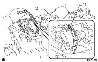
| *1 | Paint Mark |
| *2 | Timing Mark |
Apply clean engine oil to the camshaft cams and cylinder head journals.
Install the timing chain to the camshaft timing gear with the paint mark of the link aligned with the timing mark of the camshaft timing gear.
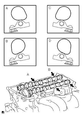
Position the 2 camshafts as shown in the illustration.
- NOTICE:
- ·
Align the paint mark and timing mark before positioning the camshaft.
·
0.344,0.563 0.458,0.563 0.458,0.563 0.677,0.854 false 1.552,0.563 1.448,0.563 1.448,0.563 1.229,0.792 false 1.385,1.135 1.604,1.26 1.604,1.26 1.604,1.344 false 0.167,0.458 0.365,0.625 0.198,0.167 10 false *1 1.604,0.469 1.802,0.635 0.198,0.167 10 false *2 1.51,1.385 1.708,1.552 0.198,0.167 10 false *3 0.781,1.76 1.042,1.938 0.26,0.177 10 false *a 2.333,1.76 2.677,1.969 0.344,0.208 10 false *b*1 Valve Stem Cap *2 Valve Rocker Arm *3 Valve Lash Adjuster *a CORRECT *b INCORRECT
Before and after positioning the No. 1 camshaft and No. 2 camshaft, check that the rocker arm is firmly set on the lash adjuster.
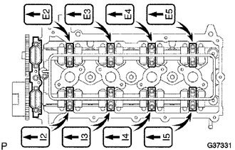
Temporarily install the No. 1 camshaft bearing cap.
Confirm the location for each camshaft bearing cap and install each one to the proper location.
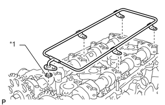
| *1 | New O-Ring |
Install a new O-ring to the No. 1 camshaft bearing cap.
Temporarily install the oil delivery pipe.
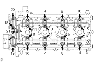
Install the 21 bolts and tighten them in the order shown in the illustration.
- Torque:
- for bolt A : 12 N*m (122 kgf*cm, 9 ft.*lbf)
- except bolt A : 16 N*m (158 kgf*cm, 11 ft.*lbf)
5.INSTALL CAMSHAFT TIMING SPROCKET
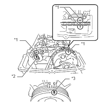
| *1 | Timing Mark |
| *2 | Knock Pin |
| *3 | Groove |
Rotate the camshaft so that the camshaft timing mark and No. 2 camshaft knock pin are as shown in the illustration.
Turn the crankshaft pulley and align its groove with the "0" timing mark of the timing chain cover.
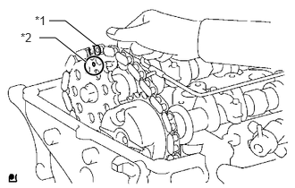
| *1 | Paint Mark |
| *2 | Timing Mark |
Install the timing chain to the camshaft timing sprocket with the paint mark aligned with the timing marks on the camshaft timing sprocket.
Align the No. 2 camshaft knock pin and camshaft timing sprocket pin hole. Then install the camshaft timing sprocket to the No. 2 camshaft.
- NOTICE:
-
If the knock pin and pin hole are difficult to align, slightly rotate the No. 2 camshaft back and forth using the hexagonal part of the camshaft. Then attempt alignment again.
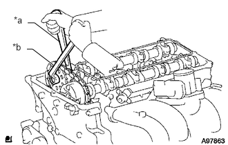
| *a | Hold |
| *b | Tighten |
Hold the camshaft with a wrench and tighten the sprocket bolt.
- Torque:
- 78 N*m (795 kgf*cm, 58 ft.*lbf)
Remove the hexagon wrench from the chain tensioner.
Apply adhesive to 2 or 3 threads of the timing chain cover plug.
- Adhesive:
Toyota Genuine Adhesive 1324, Three Bond 1324 or equivalent
- NOTICE:
-
Remove any oil from the bolt hole.
Using a 10 mm socket hexagon wrench, install the timing chain cover plug.
- Torque:
- 17 N*m (169 kgf*cm, 12 ft.*lbf)
6.INSTALL TIMING CHAIN GUIDE
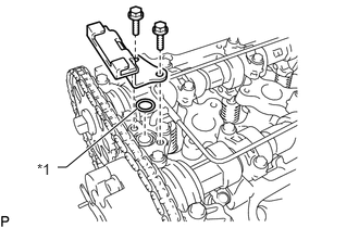
| *1 | New O-Ring |
Install a new O-ring to the camshaft bearing cap.
Install the timing chain guide with the 2 bolts.
- Torque:
- 10 N*m (102 kgf*cm, 7 ft.*lbf)
7.INSTALL CYLINDER HEAD COVER SUB-ASSEMBLY
8.INSTALL IGNITION COIL ASSEMBLY
9.INSTALL INTAKE AIR CONNECTOR
10.INSTALL FAN AND GENERATOR V BELT
11.CONNECT CABLE TO NEGATIVE BATTERY TERMINAL
- NOTICE:
-
When disconnecting the cable, some systems need to be initialized after the cable is reconnected (See page General>INTRODUCTION>REPAIR INSTRUCTION>INITIALIZATION).
12.INSPECT FOR OIL LEAK
13.INSPECT FOR COOLANT LEAK
14.INSPECT IGNITION TIMING
15.INSPECT ENGINE IDLE SPEED