Home › Engine / Hybrid System › 2TR-FE LUBRICATION › OIL PUMP › 2012.10–2014.10
RM1840EF _51 Engine / Hybrid System _009598 2TR-FE LUBRICATION _0052389 OIL PUMP A

2TR-FE LUBRICATION  OIL PUMP  INSTALLATION  


PROCEDURE

Hide 1.INSTALL ENGINE WATER PUMP ASSEMBLY

a.

Install a new gasket and the engine water pump with the 8 bolts.

Torque:
13 N*m (133 kgf*cm, 10 ft.*lbf)


Hide 2.INSTALL TIMING CHAIN COVER SUB-ASSEMBLY
a.
A222350C01
1.375,1.031 1.021,1.438 1.021,1.438 0.885,1.438 true 2.458,0.688 2.313,0.688 2.313,0.688 2.063,0.865 false 2.479,1.313 2.344,1.313 2.344,1.313 2.094,1.49 false 0.688,1.344 0.938,1.542 0.25,0.198 10 false *1 2.51,0.594 2.771,0.823 0.26,0.229 10 false *1 2.531,1.219 2.813,1.438 0.281,0.219 10 false *1
*1 New O-Ring


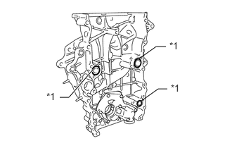
Install 3 new O-rings to the timing chain cover as shown in the illustration.


b.

Apply adhesive to the timing chain cover plug.

Adhesive:

Toyota Genuine Adhesive 1324, Three Bond 1324 or equivalent


c.

Using a 10 mm socket hexagon wrench, install the timing chain cover plug.

Torque:
17 N*m (169 kgf*cm, 12 ft.*lbf)


d.

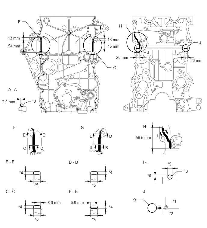
Apply seal packing to the timing chain cover in a continuous line as shown in the following illustration.

Seal packing:

Toyota Genuine Seal Packing Black, Three Bond 1207B or equivalent

A222357C01
0.771,0.75 0.896,0.75 0.896,0.75 1.292,1.24 false 3.854,2.333 3.729,2.333 3.729,2.333 3.333,1.844 false 4.26,0.896 4.354,0.896 4.354,0.896 4.531,1.156 false 6.844,1.469 6.688,1.469 6.688,1.469 6.531,1.583 false 4.802,6.896 4.969,6.896 4.969,6.896 5.156,7.073 false 6.302,5.906 6.135,5.906 6.135,5.906 5.958,6.073 false 1.073,3.51 0.969,3.51 0.969,3.51 0.792,3.604 false 4.885,1.708 4.99,1.813 4.99,1.813 5.052,1.813 true 3,1.01 3.115,1.167 0.115,0.156 10 true A 0.292,3 0.656,3.156 0.365,0.156 10 false A - A 0.198,6.521 0.771,6.677 0.573,0.156 10 false C - C 2.385,6.521 2.896,6.656 0.51,0.135 10 false B - B 2.385,5.51 2.927,5.667 0.542,0.156 10 false D - D 4.948,5.51 5.313,5.667 0.365,0.156 10 false I - I 0.198,5.5 0.688,5.667 0.49,0.167 10 false E - E 3.448,1.042 3.563,1.198 0.115,0.156 10 true A 3.646,5.01 3.792,5.156 0.146,0.146 10 false B 3.104,5 3.25,5.146 0.146,0.146 10 true B 5.896,4.469 5.99,4.615 0.094,0.146 10 true I 5.427,4.604 5.521,4.75 0.094,0.146 10 true I 1.396,5.031 1.542,5.177 0.146,0.146 10 true C 0.802,5.031 0.948,5.177 0.146,0.146 10 false C 3.781,4.615 3.927,4.771 0.146,0.156 10 false D 3.104,4.615 3.25,4.771 0.146,0.156 10 false D 1.469,4.573 1.583,4.729 0.115,0.156 10 false E 0.792,4.573 0.906,4.729 0.115,0.156 10 false E 0.625,0.667 0.74,0.823 0.115,0.156 10 false F 0.458,4.313 0.573,4.469 0.115,0.156 10 false F 3.917,2.25 4.073,2.406 0.156,0.156 10 false G 2.792,4.313 2.948,4.469 0.156,0.156 10 false G 4.125,0.813 4.385,0.969 0.26,0.156 10 false H 4.958,4.281 5.115,4.438 0.156,0.156 10 false H 6.896,1.396 7.146,1.563 0.25,0.167 10 false J 4.958,6.521 5.115,6.677 0.156,0.156 10 false J 5.094,1.719 5.281,1.906 0.188,0.188 10 true J 6.594,2 7.146,2.177 0.552,0.177 10 false 20 mm 4.021,1.896 4.583,2.063 0.563,0.167 10 false 20 mm 3.719,1.281 4.271,1.458 0.552,0.177 10 false 13 mm 0.271,1.229 0.76,1.406 0.49,0.177 10 false 13 mm 0.281,1.5 0.813,1.677 0.531,0.177 10 false 54 mm 3.719,1.51 4.208,1.688 0.49,0.177 10 false 46 mm 4.583,6.813 4.885,7 0.302,0.188 10 false *3 1.115,3.406 1.417,3.583 0.302,0.177 10 false *3 0.635,7.052 1.01,7.219 0.375,0.167 10 false *4 3.771,7.052 4.063,7.229 0.292,0.177 10 false *4 1.208,7.479 1.479,7.646 0.271,0.167 10 false *5 3.188,7.49 3.479,7.667 0.292,0.177 10 false *5 0.667,5.875 0.938,6.042 0.271,0.167 10 false *4 3.76,5.854 3.938,6.021 0.177,0.167 10 false *4 5.104,5.979 5.406,6.167 0.302,0.188 10 false *6 1.198,6.292 1.521,6.458 0.323,0.167 10 false *5 3.188,6.302 3.448,6.479 0.26,0.177 10 false *5 5.802,5.573 6.083,5.74 0.281,0.167 10 false *5 5.979,6.854 6.156,7.021 0.177,0.167 10 false *1 5.865,7.281 6.115,7.448 0.25,0.167 10 false *2 0.073,3.427 0.698,3.625 0.625,0.198 10 false 2.0 mm 1.646,6.906 2.333,7.073 0.688,0.167 10 false 6.0 mm 2.448,6.896 3.094,7.063 0.646,0.167 10 false 6.0 mm 6.375,5.823 6.635,6.01 0.26,0.188 10 false *3 4.698,4.656 5.406,4.844 0.708,0.188 10 false 56.5 mm
*1 Cylinder Head *2 Cylinder Block
*3 Seal Packing *4 Seal Packing Thickness
*5 Seal Packing Width *6 Protrusion


Application Specification:
Area Seal Packing Diameter Distance from Edge of Cover to Center of Seal Packing Seal Packing Application Length Protrusion from Cylinder Head
A - A
(Dashed line)
2.5 to 4.0 mm (0.0984 to 0.157 in.) 2.0 mm (0.0787 in.) - -
B - B
(Continuous line)
10 to 14 mm (0.394 to 0.551 in.) wide and 2.5 to 4.0 mm (0.0984 to 0.157 in.) thick 6.0 mm (0.236 in.) 46 mm (1.81 in.) from top of bolt hole -
C - C
(Continuous line)
10 to 14 mm (0.394 to 0.551 in.) wide and 2.5 to 4.0 mm (0.0984 to 0.157 in.) thick 6.0 mm (0.236 in.) 54 mm (2.13 in.) from top of bolt hole -
D - D
(Continuous line)
9.0 to 13 mm (0.354 to 0.512 in.) wide and 2.5 to 4.0 mm (0.0984 to 0.157 in.) thick - 13 mm (0.512 in.) from top of bolt hole -
E - E
(Continuous line)
9.0 to 13 mm (0.354 to 0.512 in.) wide and 2.5 to 4.0 mm (0.0984 to 0.157 in.) thick - 13 mm (0.512 in.) from top of bolt hole -
I - I
(Continuous line)
8.0 mm (0.315 in.) - 56.5 mm (2.22 in.) from bottom of cylinder head 2.0 to 3.0 mm (0.0787 to 0.118 in.)
J 10 mm (0.394 in.) - 20 mm (0.787 in.) -


NOTICE:
·

Remove any oil from the contact surface.

·

When the contact surfaces are wet, wipe them with an oil-free cloth before applying seal packing.

·

Install the timing chain cover within 3 minutes and tighten the bolts within 15 minutes after applying seal packing.

·

Do not start the engine for at least 4 hours after the installation.
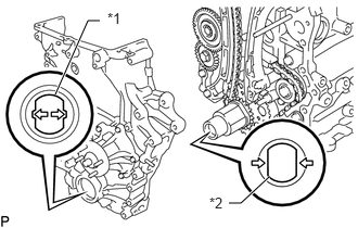


e.
A101362C01
0.958,0.198 0.844,0.198 0.844,0.198 0.531,0.906 true 2.198,1.948 2.313,1.948 2.313,1.948 2.583,1.698 true 1.031,0.094 1.208,0.25 0.177,0.156 10 false *1 2.01,1.865 2.188,2.021 0.177,0.156 10 false *2
*1 Drive Rotor Spline
*2 Crankshaft Timing Gear


Align the drive rotor spline of the oil pump and crankshaft timing gear as shown in the illustration.


f.

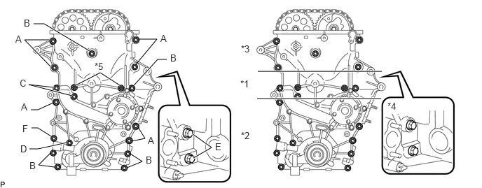
Temporarily install the timing chain cover with the 19 bolts and 2 nuts.
A101363C01
1.333,0.76 0.656,0.354 0.656,0.354 0.5,0.354 true 0.729,0.594 0.365,0.594 0.365,0.594 0.75,0.99 true 0.802,1.302 0.427,1.26 0.427,1.26 1.073,1.427 true 0.99,2.125 0.563,2.219 0.563,2.219 0.438,2.219 true 0.792,1.531 0.563,1.635 0.563,1.635 0.458,1.635 false 0.76,2.031 0.563,1.906 0.563,1.906 0.469,1.906 false 0.75,2.281 0.573,2.458 0.573,2.458 0.813,2.49 false 1.938,2.292 2.115,2.406 2.115,2.406 1.885,2.5 false 2.052,1.896 2.156,2.063 2.156,2.063 1.948,2.104 false 1.99,1.271 2.344,0.885 2.344,0.885 2.479,0.885 true 2.063,0.583 2.333,0.583 2.333,0.583 2.021,0.958 false 1.125,1.271 1.49,1.083 1.49,1.083 1.781,1.271 true 3.833,1.063 5.677,1.063 true 3.823,1.469 5.667,1.469 true 2.854,1.99 3.146,2.198 3.146,2.198 2.875,2.354 true 0.354,0.26 0.51,0.458 0.156,0.198 10 false B 2.531,0.781 2.688,0.979 0.156,0.198 10 false B 0.438,2.385 0.594,2.583 0.156,0.198 10 false B 2.167,2.302 2.323,2.5 0.156,0.198 10 false B 0.229,0.5 0.385,0.698 0.156,0.198 10 false A 2.385,0.49 2.542,0.688 0.156,0.198 10 false A 3.198,2.104 3.375,2.302 0.177,0.198 10 true E 2.198,2.01 2.354,2.208 0.156,0.198 10 false A 0.313,1.51 0.469,1.708 0.156,0.198 10 false A 0.302,2.135 0.458,2.333 0.156,0.198 10 false D 0.292,1.156 0.458,1.354 0.167,0.198 10 false C 0.333,1.833 0.49,2.031 0.156,0.198 10 false F 3.583,0.646 3.781,0.844 0.198,0.198 10 false *3 1.406,0.906 1.604,1.104 0.198,0.198 10 false *5 3.573,1.167 3.771,1.365 0.198,0.198 10 false *1 3.583,1.938 3.781,2.135 0.198,0.198 10 false *2 5.76,1.5 5.958,1.698 0.198,0.198 10 true *4
*1 Area 1 *2 Area 2
*3 Area 3 *4 Area 4
*5 Nut - -


Bolt Length:
Item Length Thread Diameter
Bolt A 75 mm (2.95 in.) 10 mm (0.394 in.)
Bolt B 75 mm (2.95 in.) 8 mm (0.315 in.)
Bolt C 90 mm (3.54 in.) 8 mm (0.315 in.)
Bolt D 95 mm (3.74 in.) 8 mm (0.315 in.)
Bolt E 35 mm (1.38 in.) 8 mm (0.315 in.)
Bolt F 75 mm (2.95 in.) 10 mm (0.394 in.)


g.

Excluding the bolts labeled A and F, tighten the bolts and nuts in this order: Area 1, Area 3, Area 2.

Torque:
for bolt C : 26 N*m (265 kgf*cm, 19 ft.*lbf)
for bolt B, D and nut : 21 N*m (214 kgf*cm, 15 ft.*lbf)


h.

Tighten the bolts labeled A in this order: Area 2 and Area 3.

Torque:
60 N*m (612 kgf*cm, 44 ft.*lbf)


i.

Tighten the bolts labeled F.

Torque:
46 N*m (469 kgf*cm, 34 ft.*lbf)


j.

Tighten the bolts labeled E in Area 4.

Torque:
21 N*m (214 kgf*cm, 15 ft.*lbf)


Hide 5.INSTALL OIL PAN SUB-ASSEMBLY

a.

Install a new O-ring.


b.

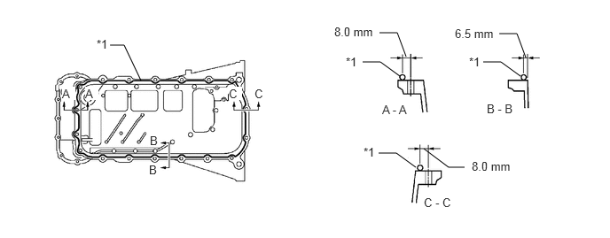
Apply seal packing in a continuous line as shown in the illustration.
A302638C01
4.698,0.896 4.469,0.729 4.469,0.729 4.26,0.729 false 6.115,0.896 5.885,0.729 5.885,0.729 5.677,0.729 false 4.885,1.969 4.656,1.802 4.656,1.802 4.448,1.802 false 4.771,0.667 4.667,0.385 4.667,0.385 4.458,0.385 false 6.177,0.677 6.073,0.396 6.073,0.396 5.865,0.396 false 5.458,1.969 5.271,1.969 5.271,1.969 4.979,1.75 false 1.656,0.948 1.458,0.531 1.458,0.531 1.292,0.531 false 4.979,2.302 5.448,2.49 0.469,0.188 10 false C - C 4.49,1.208 4.958,1.396 0.469,0.188 10 false A - A 5.719,1.198 6.188,1.385 0.469,0.188 10 false B - B 4.063,0.646 4.375,0.844 0.313,0.198 10 false *1 5.51,0.646 5.823,0.844 0.313,0.198 10 false *1 4.271,1.708 4.583,1.906 0.313,0.198 10 false *1 3.927,0.292 4.531,0.458 0.604,0.167 10 false 8.0 mm 5.344,0.313 5.948,0.479 0.604,0.167 10 false 6.5 mm 5.542,1.875 6.146,2.042 0.604,0.167 10 false 8.0 mm 1.76,1.573 1.99,1.74 0.229,0.167 10 false B 1.75,1.917 1.979,2.083 0.229,0.167 10 false B 0.729,1.021 0.885,1.177 0.156,0.156 10 true A 1,1.021 1.156,1.177 0.156,0.156 10 true A 2.688,1.021 2.844,1.177 0.156,0.156 10 true C 2.99,1.021 3.146,1.177 0.156,0.156 10 true C 1.135,0.438 1.448,0.635 0.313,0.198 10 false *1
*1 Seal Packing - -


Seal packing:

Toyota Genuine Seal Packing Black, Three Bond 1207B or equivalent


Application Specification:
Area Seal Packing Diameter Distance from Edge of Cover or Center of Bolt Hole to Center of Seal Packing
A - A and C - C 2.0 to 3.0 mm (0.0787 to 0.118 in.) 8.0 mm (0.315 in.)
B - B 2.0 to 3.0 mm (0.0787 to 0.118 in.) 6.5 mm (0.256 in.)


NOTICE:
·

Remove any oil from the contact surface.

·

Install the oil pan within 3 minutes after applying seal packing.

·

Do not start the engine for at least 4 hours after the installation.


c.
A302639C01
0.917,0.583 1.073,0.781 0.156,0.198 10 false 1 1.271,0.573 1.521,0.719 0.25,0.146 10 false 11 0.844,0.26 1.167,0.5 0.323,0.24 10 false 10 1.667,0.573 1.938,0.74 0.271,0.167 10 false 12 2.063,0.573 2.313,0.75 0.25,0.177 10 false 13 2.448,0.583 2.698,0.75 0.25,0.167 10 false 14 2.823,0.583 3.083,0.74 0.26,0.156 10 false 15 2.833,0.771 3.115,0.927 0.281,0.156 10 false 16 2.854,1.188 3.156,1.365 0.302,0.177 10 false 17 2.802,1.479 3.135,1.677 0.333,0.198 10 false 18 2.458,1.479 2.792,1.677 0.333,0.198 10 false 19 2.104,1.771 2.438,1.969 0.333,0.198 10 false 20 1.667,1.781 2,1.979 0.333,0.198 10 false 21 1.281,1.802 1.615,2 0.333,0.198 10 false 22 0.76,1.865 0.99,2.021 0.229,0.156 10 false 5 0.688,1.458 0.917,1.615 0.229,0.156 10 false 6 0.625,1.156 0.854,1.313 0.229,0.156 10 false 7 0.635,0.823 0.865,0.979 0.229,0.156 10 false 8 0.677,0.583 0.906,0.74 0.229,0.156 10 false 9 1.292,1.469 1.521,1.625 0.229,0.156 10 false 4 1.677,1.469 1.906,1.625 0.229,0.156 10 false 3 2.177,1.406 2.406,1.563 0.229,0.156 10 false 2
V100135

Bolt A
V100136

Bolt B
V100137

Nut


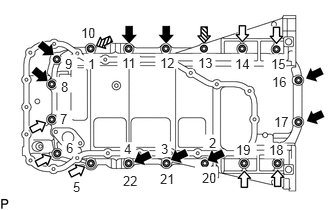
Temporarily install the oil pan with the 16 bolts and 2 nuts.

Bolt Length:
Item Length
Bolt A 20 mm (0.787 in.)
Bolt B 40 mm (1.57 in.)


d.

Uniformly tighten the 16 bolts and 2 nuts in the order shown in the illustration.

Torque:
26 N*m (265 kgf*cm, 19 ft.*lbf)


Hide 6.INSTALL OIL STRAINER SUB-ASSEMBLY

a.

Install a new gasket and the oil strainer with the bolt and 2 nuts.

Torque:
20 N*m (204 kgf*cm, 15 ft.*lbf)


Hide 7.INSTALL NO. 2 OIL PAN SUB-ASSEMBLY

a.
A302640C01
1.823,2.281 1.667,2.021 1.667,2.021 1.365,2.021 false 1.604,0.625 1.76,0.323 1.76,0.323 1.958,0.323 true 2.031,0.24 2.344,0.438 0.313,0.198 10 false *1 2.625,2.271 2.938,2.469 0.313,0.198 10 false *1 0.833,1.938 1.438,2.125 0.604,0.188 10 false 6.0 mm 0.469,0.75 0.667,0.927 0.198,0.177 10 false A 0.833,0.75 1.031,0.927 0.198,0.177 10 false A 1.469,2.917 1.927,3.125 0.458,0.208 10 false A - A
*1 Seal Packing


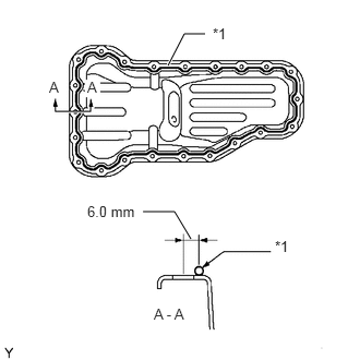
Apply seal packing in a continuous line as shown in the illustration.

Seal packing:

Toyota Genuine Seal Packing Black, Three Bond 1207B or equivalent


Application Specification:
Seal Packing Diameter Distance from Edge of Cover or Center of Bolt Hole to Center of Seal Packing
2.5 to 3.5 mm (0.0984 to 0.138 in.) 6.0 mm (0.236 in.)


NOTICE:
·

Remove any oil from the contact surface.

·

Install the oil pan within 3 minutes after applying seal packing.

·

Do not start the engine for at least 4 hours after the installation.


b.

Temporarily install the No. 2 oil pan with the 20 bolts and 2 nuts.
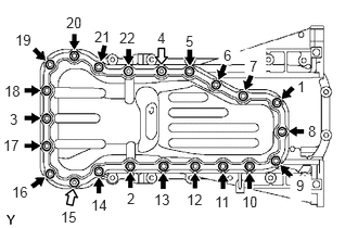

c.
A302641C01
0.146,0.302 0.458,0.5 0.313,0.198 10 false 19 0.635,0.135 0.948,0.333 0.313,0.198 10 false 20 0.906,0.271 1.219,0.469 0.313,0.198 10 false 21 1.146,0.281 1.458,0.479 0.313,0.198 10 false 22 1.51,0.281 1.688,0.479 0.177,0.198 10 false 4 0.042,0.792 0.354,0.99 0.313,0.198 10 false 18 0.031,1.313 0.344,1.51 0.313,0.198 10 false 17 1.781,0.313 1.958,0.51 0.177,0.198 10 false 5 2.146,0.448 2.323,0.646 0.177,0.198 10 false 6 2.396,0.552 2.573,0.75 0.177,0.198 10 false 7 2.854,0.75 3.031,0.948 0.177,0.198 10 false 1 2.958,1.177 3.115,1.406 0.156,0.229 10 false 8 2.844,1.698 3,1.927 0.156,0.229 10 false 9 0.094,1.063 0.271,1.26 0.177,0.198 10 false 3 0.115,1.76 0.427,1.958 0.313,0.198 10 false 16 0.583,2 0.885,2.177 0.302,0.177 10 false 15 0.875,1.885 1.177,2.063 0.302,0.177 10 false 14 1.219,1.823 1.396,1.99 0.177,0.167 10 false 2 1.479,1.833 1.781,2.01 0.302,0.177 10 false 13 1.792,1.833 2.094,2.01 0.302,0.177 10 false 12 2.063,1.854 2.365,2.031 0.302,0.177 10 false 11 2.323,1.854 2.625,2.031 0.302,0.177 10 false 10
V100135

Bolt
V100136

Nut


Uniformly tighten the 20 bolts and 2 nuts in the order shown in the illustration.

Torque:
9.0 N*m (92 kgf*cm, 80 in.*lbf)


d.

Install a new gasket and the drain plug.

Torque:
38 N*m (382 kgf*cm, 28 ft.*lbf)


Hide 8.INSTALL CRANKSHAFT PULLEY

a.
G037341C01
1.188,0.792 0.573,0.76 0.573,0.76 0.958,0.896 true 0.25,0.677 0.573,0.833 0.323,0.156 10 false SST 0.833,1.74 1.042,1.906 0.208,0.167 10 false *a
*a Hold
V100135

Turn


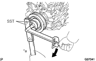
Align the key groove of the pulley with the pulley set key and slide on the crankshaft pulley.


b.

Using SST, install a new crankshaft pulley bolt.

SST
09213-54015  (91651-60855)
09330-00021  

Torque:
260 N*m (2651 kgf*cm, 192 ft.*lbf)

NOTICE:

Do not reuse the pulley bolt.


Hide 10.INSTALL CYLINDER HEAD COVER SUB-ASSEMBLY

a.

Install 2 new cover gaskets to the head cover.
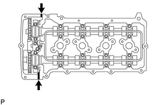

b.
A302642C01
0.802,1.76 0.802,1.813 false
V100135

Seal Packing


Apply seal packing to the places shown in the illustration.

Seal packing:

Toyota Genuine Seal Packing Black, Three Bond 1207B or equivalent


Seal packing diameter:

4.0 mm (0.157 in.)


NOTICE:
·

Remove any oil from the contact surface.

·

Install the head cover within 3 minutes after applying seal packing.

·

Do not start the engine for at least 4 hours after the installation.


c.

Temporarily install the cylinder head cover with the 19 bolts and 2 nuts.
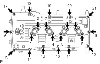

d.
A302643N01
0.115,0.146 0.427,0.344 0.313,0.198 10 false 17 0.938,0.052 1.25,0.25 0.313,0.198 10 false 18 1.625,0.125 1.938,0.323 0.313,0.198 10 false 19 2.323,0.125 2.635,0.323 0.313,0.198 10 false 20 3.177,0.219 3.427,0.417 0.25,0.198 10 false 21 0.073,1.156 0.385,1.354 0.313,0.198 10 false 16 0.146,1.885 0.458,2.083 0.313,0.198 10 false 15 0.948,1.958 1.26,2.156 0.313,0.198 10 false 14 1.406,1.854 1.719,2.052 0.313,0.198 10 false 13 1.927,1.865 2.24,2.063 0.313,0.198 10 false 12 2.292,1.865 2.604,2.063 0.313,0.198 10 false 11 3.156,1.792 3.427,1.99 0.271,0.198 10 false 10 3.271,1.146 3.406,1.333 0.135,0.188 10 false 9 2.792,1.427 2.927,1.615 0.135,0.188 10 false 8 2.563,0.563 2.698,0.75 0.135,0.188 10 false 7 2.271,0.542 2.406,0.729 0.135,0.188 10 false 6 1.552,0.573 1.688,0.76 0.135,0.188 10 false 3 1.271,0.563 1.406,0.75 0.135,0.188 10 false 2 1.031,1.417 1.167,1.604 0.135,0.188 10 false 1 1.792,1.448 1.927,1.635 0.135,0.188 10 false 4 2.115,1.448 2.25,1.635 0.135,0.188 10 false 5

Uniformly tighten the 19 bolts and 2 nuts in the order shown in the illustration.

Torque:
9.0 N*m (92 kgf*cm, 80 in.*lbf)


e.

In numerical order, confirm that the bolts labeled 1 to 8 are tightened to the specified torque. Tighten the bolts as necessary.


Hide 13.INSTALL NO. 1 IDLER PULLEY SUB-ASSEMBLY

Hide 14.INSTALL V-RIBBED BELT TENSIONER ASSEMBLY

Hide 17.INSTALL NO. 1 COMPRESSOR MOUNTING BRACKET (w/ Air Conditioning System)

Hide 21.INSTALL FUEL DELIVERY PIPE SUB-ASSEMBLY