2KD-FTV FUEL FUEL INJECTOR(w/o DPF) INSTALLATION
CAUTION / NOTICE / HINT
- NOTICE:
- ·
When replacing the injectors (including shuffling the injectors between the cylinders), common rail or cylinder head, it is necessary to replace the injection pipes with new ones.
·When replacing the fuel supply pump, common rail, cylinder block, cylinder head, cylinder head gasket or timing gear case, it is necessary to replace the fuel inlet pipe with a new one.
·After removing the injection pipes, clean them with a brush and compressed air.
PROCEDURE

 1.INSTALL INJECTOR ASSEMBLY
- NOTICE:
-
Be sure to install each injector, No. 1 nozzle holder clamp, washer and bolt in its original position.
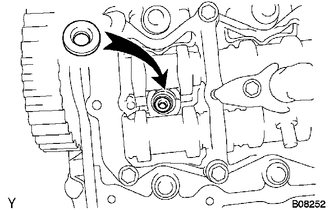
Install 4 new injection nozzle seats to the cylinder head.
Apply a small amount of clean engine oil to 4 new O-rings.
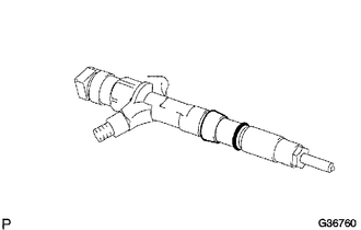
| *1 | New O-Ring |
Install an O-ring to each injector as shown in the illustration.
Insert the 4 injectors into the cylinder head.
- NOTICE:
- ·
Insert the injector until it touches the injection nozzle seat surface.
·After installing the injector to the cylinder head, the O-ring may prevent the injector from fully seating. If so, pull out the injector and reinstall it.
·Always return an injector to the same place it was removed from.
For an injector that has been replaced with a new injector, register the injector compensation code.
w/ EGR Cooler: (See page Engine / Hybrid System>2KD-FTV ENGINE CONTROL>ECD SYSTEM(w/ EGR Cooler)>REGISTRATION)
w/o EGR Cooler: (See page Engine / Hybrid System>2KD-FTV ENGINE CONTROL>ECD SYSTEM(w/o EGR Cooler)>REGISTRATION)
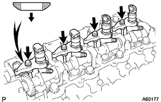
| *1 | Washer |
| *a | Downward |
Temporarily install 4 new washers and the 4 No. 1 nozzle holder clamps with the 4 bolts.
- NOTICE:
-
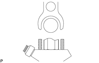 1.522,0.318 0.708,0.318 false 1.345,1.477 0.895,1.477 0.895,1.477 0.895,0.321 false 0.495,0.229 0.683,0.38 0.188,0.15 10 *1
*1 No. 1 Nozzle Holder Clamp
- ·
The fork portion of the nozzle holder clamp must be set on the injector.
·Before tightening the bolts, check that the No. 1 nozzle holder clamps are set properly.
·To fasten the clamp bolts, first tighten them by hand until they cannot be turned further. Then, tighten the bolts to the specified torque in a following step.
·When tightening the bolts, pay attention so as not to tilt the bolt or clamp.
·Do not reuse the washer.
·If the nozzle leakage pipe is accidentally tightened beyond the torque specification, it must be replaced.
- HINT:
-
Apply a small amount of engine oil to the threads and under the heads of the clamp bolts.
Temporarily install the 4 injection pipes with the union nuts.
- HINT:
-
To position the injectors, loosely tighten the union nuts.
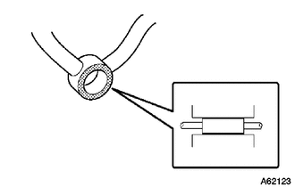
Check the nozzle leakage pipe. Check that there are no scratches or dents on the 5 union seal surfaces.
If scratches or dents are present, replace the nozzle leakage pipe.
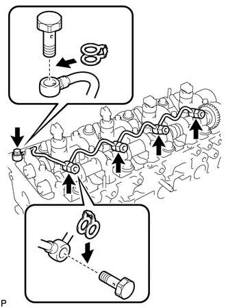
| *1 | Union Bolt |
| *2 | New Gasket |
| *3 | Injector Hollow Screw |
Set the nozzle leakage pipe and 5 new gaskets in place.
Apply a small amount of oil to the 4 injector hollow screws and union bolt.
Temporarily install the nozzle leakage pipe with the 4 injector hollow screws and union bolt.
Tighten the 4 holder clamp bolts.
- Torque:
- 22 N*m (220 kgf*cm, 16 ft.*lbf)
Remove the 4 injection pipes.
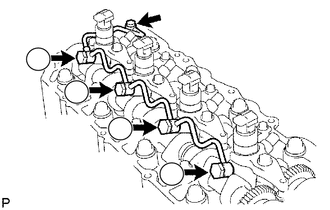
| *1 | Union Bolt |
Tighten the 4 injector hollow screws in order from 1 to 4.
- Torque:
- 16 N*m (163 kgf*cm, 12 ft.*lbf)
- NOTICE:
-
If an injector hollow screw is accidentally tightened beyond the torque specification, it must be replaced.
Tighten the union bolt.
- Torque:
- 13 N*m (127 kgf*cm, 9 ft.*lbf)
- NOTICE:
-
If the union bolt is accidentally tightened beyond the torque specification, it must be replaced.
2.INSPECT FOR FUEL LEAK
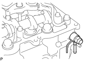
Check that there are no leaks from the nozzle leakage pipe connection.
Install the gasket and No. 2 nozzle leakage pipe to the cylinder head with SST (check valve).
- Part No.:
23762-27010 (No. 2 nozzle leakage pipe)
- SST
- 09280-00010
- Torque:
- 21 N*m (214 kgf*cm, 15 ft.*lbf)
Apply a small amount of soapy water (or other fluid for detecting fuel leakage) on the nozzle leakage pipe connection.
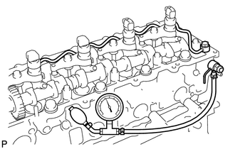
Install SST (turbocharger pressure gauge) to the fuel return side of the leakage pipe and maintain 100 kPa (1.0 kgf/cm2, 15 psi) of pressure for 60 seconds to check that no bubbles form.
- SST
- 09992-00242
- NOTICE:
-
Before checking for leakage, be sure to remove the ball and spring in the check valve.
After checking for fuel leaks, wipe off the soapy water from the leakage pipe connection.
Remove SST, the No. 2 nozzle leakage pipe and gasket.
- NOTICE:
-
Never reinstall the disassembled check valve to the engine.
3.INSTALL CYLINDER HEAD COVER SUB-ASSEMBLY
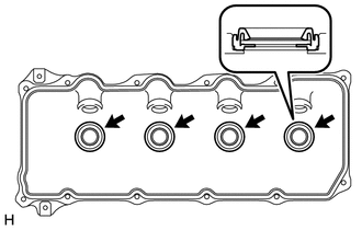
| *1 | No. 3 Cylinder Head Cover Gasket |
| *2 | Cylinder Head Cover |
Install 4 new No. 3 cylinder head cover gaskets to the cylinder head cover in the directions shown in the illustration.
- NOTICE:
- ·
Do not install the No. 3 cylinder head cover gaskets at an angle.
·Check that there is no foreign matter at the installation location of the No. 3 cylinder head cover gaskets.
Remove any old seal packing (FIPG material) from the cylinder head.
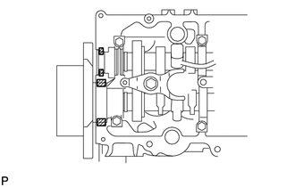

|
Seal Packing |
Apply seal packing to the specific areas shown in the illustration.
- Seal packing:
Toyota Genuine Seal Packing Black, Three Bond 1207B or equivalent
- NOTICE:
- ·
Remove any oil from the contact surface.
·Install the head cover within 3 minutes after applying seal packing.
·Do not start the engine for at least 2 hours after installing the seal packing.
Install a new cylinder head cover gasket and the cylinder head cover with the 10 bolts and 2 nuts.
- Torque:
- 9.0 N*m (92 kgf*cm, 80 in.*lbf)
Install 4 new nozzle holder seals.
Connect the ventilation hose.
w/ EGR Cooler:
Connect the 4 injector connectors and install the 3 bolts.
- Torque:
- 13 N*m (127 kgf*cm, 9 ft.*lbf)
w/o EGR Cooler:
Connect the 4 injector connectors.
4.INSTALL NO. 2 NOZZLE LEAKAGE PIPE ASSEMBLY
5.INSTALL NO. 4 INJECTION PIPE SUB-ASSEMBLY
- NOTICE:
- ·
When replacing an injector, it is necessary to replace the 4 injection pipes with new ones.
·Keep the joints of the injection pipe clean.
Temporarily install the No. 4 injection pipe with the union nuts.
w/ EGR Cooler:
Install the bolt.
- Torque:
- 5.0 N*m (51 kgf*cm, 44 in.*lbf)
- NOTICE:
- ·
If an injection pipe clamp is removed from the No. 4 injection pipe, replace the injection pipe clamp with a new one.
·Make sure that the inner rubbers of the injection pipe fit inside the clamps.
·When installing the pipe, check that the inner rubbers and the clamps are in their proper positions.
w/o EGR Cooler:
Install the 2 bolts.
- Torque:
- 13 N*m (130 kgf*cm, 9 ft.*lbf)
- NOTICE:
- ·
If an injection pipe clamp is removed from the No. 4 injection pipe, replace the injection pipe clamp with a new one.
·Make sure that the inner rubbers of the injection pipe fit inside the clamps.
·When installing the pipe, check that the inner rubbers and the clamps are in their proper positions.
Using a 17 mm union nut wrench, tighten the injection pipe union nuts on the common rail side.
- Torque:
- 35 N*m (357 kgf*cm, 26 ft.*lbf)
- NOTICE:
-
Use the formula to calculate special torque values for situations where a union nut wrench is combined with a torque wrench (See page General>INTRODUCTION>REPAIR INSTRUCTION>PRECAUTION).
Using a union nut wrench, tighten the injection pipe union nuts on the injector side.
- Torque:
- 35 N*m (357 kgf*cm, 26 ft.*lbf)
- NOTICE:
-
Use the formula to calculate special torque values for situations where a union nut wrench is combined with a torque wrench (See page General>INTRODUCTION>REPAIR INSTRUCTION>PRECAUTION).
6.TEMPORARILY INSTALL ELECTRIC EGR CONTROL VALVE ASSEMBLY WITH NO. 2 EGR VALVE AND EGR COOLER (w/ EGR Cooler)
7.INSTALL NO. 2 INTAKE AIR CONNECTOR (w/ EGR Cooler)
8.TEMPORARILY INSTALL INTAKE AIR CONNECTOR (w/ EGR Cooler)
9.TIGHTEN NO. 2 INTAKE AIR CONNECTOR AND INTAKE AIR CONNECTOR (w/ EGR Cooler)
10.TIGHTEN INTAKE AIR CONNECTOR AND INTAKE MANIFOLD (w/ EGR Cooler)
11.TIGHTEN EGR COOLER (w/ EGR Cooler)
12.INSTALL NO. 2 INTAKE AIR CONNECTOR BRACKET (w/ EGR Cooler)
13.INSTALL ELECTRIC VACUUM REGULATING VALVE ASSEMBLY (w/ EGR Cooler)
14.CONNECT NO. 3 WATER BY-PASS PIPE (w/ EGR Cooler)
15.INSTALL NO. 1, NO. 2 AND NO. 3 INJECTION PIPE SUB-ASSEMBLY
- NOTICE:
- ·
When replacing an injector, it is necessary to replace the 4 injection pipes with new ones.
·Keep the joints of the injection pipes clean.
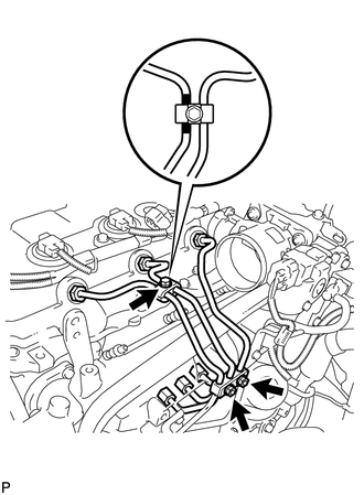
Temporarily install the No. 1, No. 2 and No. 3 injection pipes with the union nuts.
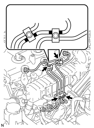
| *1 | No. 2 Injection Pipe |
| *2 | No. 2 Injection Pipe Clamp |
| *3 | No. 3 Injection Pipe Clamp |
| *4 | Painted Mark |
w/ EGR Cooler:
Install the No. 2 and No. 3 injection pipe clamps with the 2 bolts and 2 nuts as shown in the illustration.
- Torque:
- 5.0 N*m (51 kgf*cm, 44 in.*lbf)
- HINT:
-
If the painted mark on the No. 2 injection pipe has disappeared, use the illustration as a reference to install the clamps.
| *1 | No. 1 Injection Pipe |
| *2 | No. 2 Injection Pipe Clamp |
| *3 | No. 3 Injection Pipe Clamp |
| *4 | Painted Mark |
w/o EGR Cooler:
Install the No. 2 and No. 3 injection pipe clamps with the bolt and 2 nuts as shown in the illustration.
- Torque:
- 5.0 N*m (51 kgf*cm, 44 in.*lbf)
- HINT:
-
If the painted mark on the No. 1 injection pipe has disappeared, use the illustration as a reference to install the clamps.
Using a 17 mm union nut wrench, tighten the injection pipe union nuts on the common rail side.
- Torque:
- 35 N*m (357 kgf*cm, 26 ft.*lbf)
- NOTICE:
-
Use the formula to calculate special torque values for situations where a union nut wrench is combined with a torque wrench (See page General>INTRODUCTION>REPAIR INSTRUCTION>PRECAUTION).
Using a 17 mm union nut wrench, tighten the injection pipe union nuts on the injector side.
- Torque:
- 35 N*m (357 kgf*cm, 26 ft.*lbf)
- NOTICE:
-
Use the formula to calculate special torque values for situations where a union nut wrench is combined with a torque wrench (See page General>INTRODUCTION>REPAIR INSTRUCTION>PRECAUTION).
16.CONNECT NO. 4 WATER BY-PASS HOSE (w/ EGR Cooler)
17.CONNECT NO. 3 WATER BY-PASS HOSE (w/ EGR Cooler)
18.INSTALL DIESEL THROTTLE BODY ASSEMBLY (w/ EGR Cooler)
19.INSTALL NO. 2 AIR CLEANER PIPE SUB-ASSEMBLY (w/o EGR Cooler)
20.CONNECT CABLE TO NEGATIVE BATTERY TERMINAL
- NOTICE:
-
When disconnecting the cable, some systems need to be initialized after the cable is reconnected (See page General>INTRODUCTION>REPAIR INSTRUCTION>INITIALIZATION).
21.ADD ENGINE COOLANT (w/ EGR Cooler)
22.BLEED AIR FROM FUEL SYSTEM
23.PERFORM REGISTRATION
Perform registration of injector compensation codes.
w/ EGR Cooler: (See page Engine / Hybrid System>2KD-FTV ENGINE CONTROL>ECD SYSTEM(w/ EGR Cooler)>REGISTRATION)
w/o EGR Cooler: (See page Engine / Hybrid System>2KD-FTV ENGINE CONTROL>ECD SYSTEM(w/o EGR Cooler)>REGISTRATION)
Perform registration of pilot quantity learning.
w/ EGR Cooler: (See page Engine / Hybrid System>2KD-FTV ENGINE CONTROL>ECD SYSTEM(w/ EGR Cooler)>REGISTRATION)
w/o EGR Cooler: (See page Engine / Hybrid System>2KD-FTV ENGINE CONTROL>ECD SYSTEM(w/o EGR Cooler)>REGISTRATION)
24.INSPECT FOR COOLANT LEAK (w/ EGR Cooler)
25.INSPECT FOR FUEL LEAK
26.INSPECT FOR OIL LEAK
27.INSPECT ENGINE OIL LEVEL