A343F AUTOMATIC TRANSMISSION / TRANSAXLE AUTOMATIC TRANSMISSION ASSEMBLY REMOVAL
PROCEDURE

 1. PRECAUTION
- NOTICE:
-
After turning the ignition switch off, waiting time may be required before disconnecting the cable from the battery terminal. Therefore, make sure to read the disconnecting the cable from the battery terminal notice before proceeding with work (See page General>INTRODUCTION>REPAIR INSTRUCTION>PRECAUTION).
2.DISCONNECT CABLE FROM NEGATIVE BATTERY TERMINAL
- NOTICE:
-
When disconnecting the cable, some systems need to be initialized after the cable is reconnected (See page General>INTRODUCTION>REPAIR INSTRUCTION>INITIALIZATION).
3.REMOVE CONSOLE BOX ASSEMBLY
4.REMOVE SHIFT LEVER BOOT ASSEMBLY
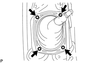
Remove the 4 screws and shift lever boot assembly.
5.REMOVE TRANSFER HIGH AND LOW SHIFT LEVER ASSEMBLY
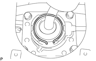
Fold back the transfer front drive shift boot.
Using needle-nose pliers, remove the snap ring and pull out the shift lever.
- HINT:
-
Move the transfer shift lever to the H4 position.
6.REMOVE NO. 1 ENGINE UNDER COVER
7.REMOVE NO. 2 ENGINE UNDER COVER
8.REMOVE NO. 3 ENGINE UNDER COVER
9.REMOVE FRONT EXHAUST PIPE ASSEMBLY
10.REMOVE FRONT PROPELLER SHAFT ASSEMBLY
11.REMOVE PROPELLER WITH CENTER BEARING SHAFT ASSEMBLY
12.DRAIN AUTOMATIC TRANSMISSION FLUID
13.REMOVE TRANSMISSION OIL FILLER TUBE SUB-ASSEMBLY
14.REMOVE STARTER ASSEMBLY
15.DISCONNECT OIL COOLER TUBE
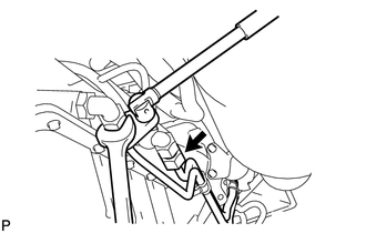
Using a union nut wrench, disconnect the outlet oil cooler tube and inlet oil cooler tube.
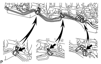
Remove the 3 bolts and 3 clamps.
16.DISCONNECT TRANSMISSION CONTROL CABLE ASSEMBLY
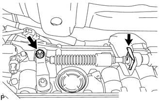
Remove the nut and clip, and disconnect the transmission control cable.
17.SUPPORT AUTOMATIC TRANSMISSION ASSEMBLY
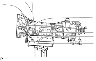
Support the automatic transmission assembly with a transmission jack.
18.REMOVE NO. 3 FRAME CROSSMEMBER SUB-ASSEMBLY
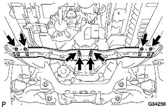
Remove the 4 set bolts of the rear No. 1 engine mounting insulator.
Remove the 4 nuts, 4 bolts and No. 3 frame crossmember.
19.REMOVE REAR NO. 1 ENGINE MOUNTING INSULATOR
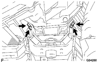
Remove the 4 bolts and engine mounting insulator.
20.DISCONNECT WIRE HARNESS AND CONNECTOR
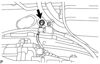
Remove the nut and disconnect the ground cable.
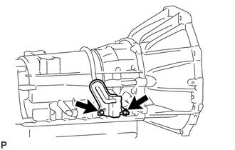
Remove the 2 bolts and heat insulator.
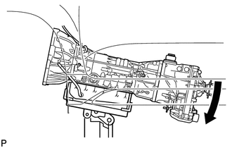
Tilt the transmission downward.
- NOTICE:
-
Make sure the cooling fan does not contact the fan shroud.
Disconnect the park/neutral position switch connector, transmission wire connector, 2 speed sensor connectors and transfer control side connector.
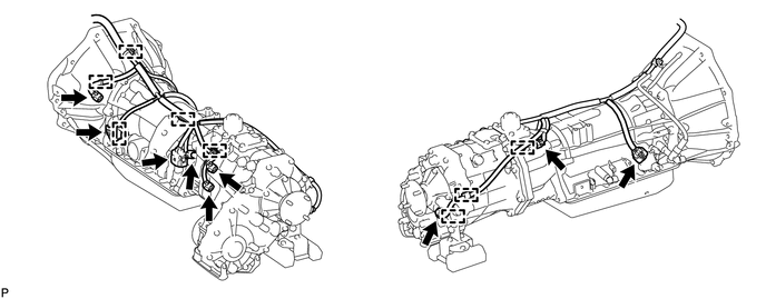
Disconnect the 8 wire harness clamps.
21.REMOVE DRIVE PLATE AND TORQUE CONVERTER SETTING BOLT
Remove the flywheel housing dust seal.
Turn the crankshaft to gain access to each bolt.
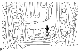
Hold the crankshaft pulley bolt with a wrench and remove the 6 torque converter setting bolts.
22.REMOVE MANIFOLD STAY
23.REMOVE AUTOMATIC TRANSMISSION ASSEMBLY
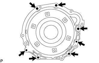
Remove the 7 bolts and automatic transmission assembly.
- NOTICE:
-
Do not use excess force to pry off the transmission assembly.
24.REMOVE TRANSMISSION CONTROL CABLE BRACKET
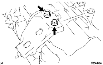
Remove the 2 bolts and control cable bracket from the transmission.
25.REMOVE TRANSFER ASSEMBLY
26.REMOVE TORQUE CONVERTER ASSEMBLY
Remove the torque converter from the automatic transmission assembly.