CLUTCH CLUTCH MASTER CYLINDER INSTALLATION
PROCEDURE

 1.INSTALL MASTER CYLINDER PUSH ROD CLEVIS
Install the lock nut and master cylinder push rod clevis to the push rod.
- HINT:
-
Tighten the lock nut to the specified torque when adjusting the clutch pedal.
2.INSTALL CLUTCH MASTER CYLINDER ASSEMBLY
Install a new gasket and the clutch master cylinder assembly with the 2 nuts.
- Torque:
- 14 N*m (145 kgf*cm, 10 ft.*lbf)
3.CONNECT CLUTCH MASTER CYLINDER PUSH ROD CLEVIS
4.CONNECT CLUTCH MASTER CYLINDER TO FLEXIBLE HOSE TUBE
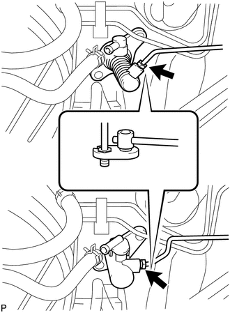
| *A | for Resin Type |
| *B | for Aluminum Type |
Using a union nut wrench, connect the clutch master cylinder to flexible hose tube.
- Torque:
- 15 N*m (155 kgf*cm, 11 ft.*lbf)
- NOTICE:
-
Use the formula to calculate special torque values for situations where a union nut wrench is combined with a torque wrench (See page General>INTRODUCTION>REPAIR INSTRUCTION>PRECAUTION).
5.CONNECT CLUTCH RESERVOIR HOSE
Connect the clutch reservoir hose to the clutch master cylinder assembly with the clip.
- NOTICE:
-
Connect the clutch reservoir hose so that it is not twisted.
6.INSTALL COMBINATION METER ASSEMBLY
7.BLEED AIR FROM CLUTCH PIPE LINE
(See page Drivetrain>CLUTCH>CLUTCH SYSTEM>BLEEDING)
8.CHECK FOR CLUTCH FLUID LEAKAGE
- HINT:
-
Check for leaks in the clutch system.
9.INSPECT AND ADJUST CLUTCH PEDAL ASSEMBLY
(See page Drivetrain>CLUTCH>CLUTCH PEDAL>ADJUSTMENT)
10.CHECK FLUID LEVEL IN RESERVOIR