AXLE AND DIFFERENTIAL FRONT DIFFERENTIAL CARRIER ASSEMBLY REASSEMBLY
PROCEDURE

 1.INSTALL FRONT DIFFERENTIAL SIDE GEAR SHAFT RH BEARING
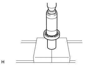
Using SST and a press, press in the shaft RH bearing.
- SST
- 09223-00010
Using a snap ring expander, install the snap ring.
- HINT:
-
Install the snap ring securely.
2.INSTALL DIFFERENTIAL SIDE GEAR SHAFT SUB-ASSEMBLY RH
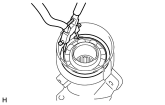
Install the shaft to the differential tube.
Using a snap ring expander, install a new snap ring.
- HINT:
-
Install the snap ring securely.
3.INSTALL DIFFERENTIAL SIDE GEAR SHAFT OIL SEAL RH
4.INSTALL DIFFERENTIAL CLUTCH HUB
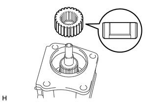
Install the clutch hub to the side gear inter shaft.
Using snap ring pliers, install the snap ring.
- HINT:
-
Install the snap ring securely.
- NOTICE:
-
Make sure to install the differential clutch hub in the correct direction.
5.INSTALL FRONT DIFFERENTIAL SIDE GEAR NEEDLE ROLLER BEARING
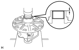
Using SST and a press, press in 2 new bearings.
- SST
- 09950-60010 (09951-00380)
- Needle roller bearing depth:
1.7 +/-0.3 mm (0.0669 +/-0.0118 in.)
6.ASSEMBLE DIFFERENTIAL CASE
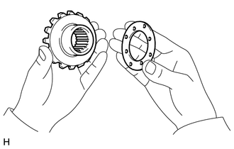
Install 2 thrust washers to the 2 side gears.
- HINT:
-
Using the table below, select 2 thrust washers which will ensure that the backlash is within the specifications.
- Standard Thrust Washer Thickness:
Thickness mm (in.) Thickness mm (in.) 1.48 to 1.52 (0.0583 to 0.0598) 1.73 to 1.77 (0.0681 to 0.0696) 1.53 to 1.57 (0.0603 to 0.0618) 1.78 to 1.82 (0.0701 to 0.0716) 1.58 to 1.62 (0.0622 to 0.0637) 1.83 to 1.87 (0.0720 to 0.0736) 1.63 to 1.67 (0.0642 to 0.0657) 1.88 to 1.92 (0.0740 to 0.0755) 1.68 to 1.72 (0.0662 to 0.0677) -
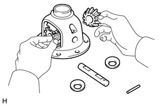
Install the 2 side gears, 2 pinion gears, 2 side gear thrust washers, 2 pinion gear thrust washers and pinion shaft to the differential case.
- HINT:
-
Align the holes of the differential case and pinion shaft.
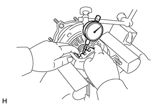
Measure the side gear backlash.
Using a dial indicator, measure the side gear backlash while holding one pinion gear toward the differential case.
- Backlash:
0.15 mm (0.00591 in.) or less
If the backlash is not as specified, install 2 side gear thrust washers with different thicknesses.
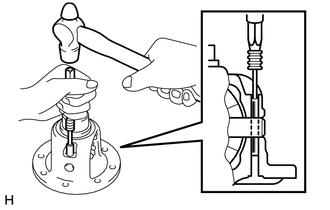
Using a pin punch and hammer, tap in the straight pin through the differential case and hole of the pinion shaft.
Stake the differential case.
7.INSTALL DIFFERENTIAL RING GEAR
Clean the contact surface of the differential case and ring gear.
Heat the ring gear in boiling water that is approximately 100°C (212°F).
Carefully remove the ring gear from the boiling water.
After the moisture on the ring gear has completely evaporated, quickly install the ring gear to the differential case.
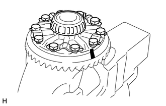
| *a | Matchmark |
Align the matchmarks on the ring gear and differential case.
After the ring gear cools down, apply thread lock adhesive to the 10 set bolts and install them.
- Thread lock:
Toyota Genuine Adhesive 1360K, Three Bond 1360K or equivalent
- Torque:
- 97 N*m (984 kgf*cm, 71 ft.*lbf)
8.INSTALL FRONT DIFFERENTIAL CASE BEARING
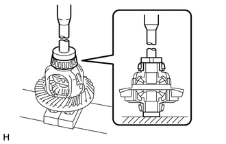
Using SST and a press, press the bearing onto the differential case.
- SST
- 09950-60010 (09951-00520, 09951-00610)
09950-70010 (09951-07150)
9.INSTALL FRONT DIFFERENTIAL CASE BEARING
- HINT:
-
When replacing the 2 differential case bearings, install the thinnest washer to each bearing. When reusing the bearings, install a new washer of the same thickness as the one that was removed to each bearing.
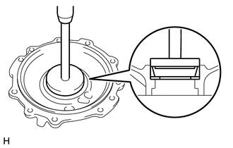
Using SST and a press, press in the case bearing (outer) to the differential side bearing retainer.
- SST
- 09950-60020 (09951-00810)
09950-70010 (09951-07150)
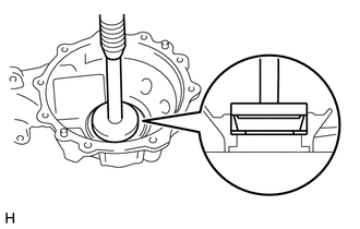
Using SST and a press, press in the case bearing (outer) to the differential carrier.
- SST
- 09950-60020 (09951-00810)
09950-70010 (09951-07150)
10.INSTALL BEARING OUTER RACE
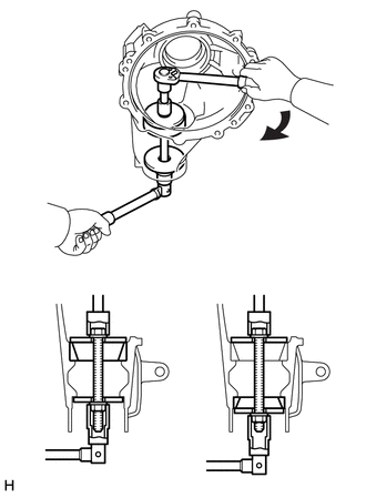
| *a | for Front |
| *b | for Rear |
| *c | Turn |
| *d | Hold |
Using SST, install the outer race front.
- SST
- 09950-60020 (09951-00720, 09951-00890)
Using a brass bar and hammer, tap in a new oil storage ring.
Using SST, install the outer race rear.
- SST
- 09950-60020 (09951-00720, 09951-00890)
11.INSTALL FRONT DRIVE PINION FRONT TAPERED ROLLER BEARING
Install the washer to the drive pinion.
- HINT:
-
First, install a washer that has the same thickness as the removed washer. After checking the tooth contact pattern, replace the washer with one of a different thickness if necessary.
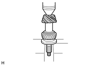
Using SST and a press, press the front bearing onto the drive pinion.
- SST
- 09506-30012
12.ADJUST DIFFERENTIAL DRIVE PINION PRELOAD
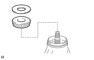
Install the drive pinion, rear drive pinion tapered roller bearing (inner) and oil slinger.
- HINT:
-
Install the spacer and oil seal after adjusting the gear contact pattern.
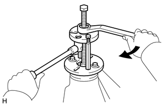
| *a | Turn |
| *b | Hold |
Using SST, install the companion flange.
- SST
- 09950-30012 (09951-03010, 09953-03010, 09954-03010, 09955-03030, 09956-03020)
- NOTICE:
-
Before using SST (center bolt), apply hypoid gear oil to its threads and tip.
Adjust the drive pinion preload by tightening the companion flange nut.
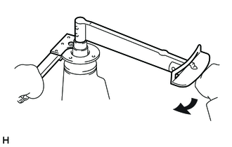
| *a | Turn |
| *b | Hold |
Using SST to hold the flange in place, tighten the nut.
- SST
- 09330-00021 (09330-00030)
- Torque:
- 370 N*m (3773 kgf*cm, 273 ft.*lbf)
or less
- NOTICE:
- ·
As there is no spacer, tighten the nut a little at a time. Be careful not to overtighten it.
·Apply hypoid gear oil LSD to drive pinion thread and nut seat face.
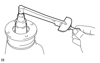
Using a torque wrench, measure the preload.
- Standard Preload (Starting Torque):
Item Specified Condition New bearing 0.7 to 1.2 N*m (8 to 12 kgf*cm, 7 to 10 in.*lbf) Reused bearing 0.2 to 0.4 N*m (2 to 4 kgf*cm, 2 to 3 in.*lbf)
- NOTICE:
- ·
For a more accurate measurement, rotate the bearing forward and backward several times before measuring.
·Record the differential drive pinion preload for the total preload measurement.
13.INSTALL DIFFERENTIAL CASE ASSEMBLY
14.ADJUST DIFFERENTIAL RING GEAR BACKLASH
Install the side bearing retainer with the 10 bolts.
- Torque:
- 50 N*m (510 kgf*cm, 37 ft.*lbf)
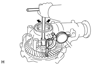
Using SST and a dial indicator, measure the ring gear backlash.
- SST
- 09564-33010
- Standard backlash:
0.11 to 0.21 mm (0.00433 to 0.00826 in.)
If the backlash is not as specified, adjust it by either increasing or decreasing the number of washers on both sides equally.
- HINT:
-
There should be no clearance between the plate washer and case. Make sure that the ring gear has backlash.
- Standard Washer Thickness:
Thickness mm (in.) Thickness mm (in.) Thickness mm (in.) 1.57 to 1.59 (0.0618 to 0.0625) 1.79 to 1.81 (0.0705 to 0.0712) 2.01 to 2.03 (0.0792 to 0.0799) 1.59 to 1.61 (0.0626 to 0.0633) 1.81 to 1.83 (0.0713 to 0.0720) 2.03 to 2.05 (0.0800 to 0.0807) 1.61 to 1.63 (0.0634 to 0.0641) 1.83 to 1.85 (0.0720 to 0.0728) 2.05 to 2.07 (0.0808 to 0.0814) 1.63 to 1.65 (0.0642 to 0.0649) 1.85 to 1.87 (0.0729 to 0.0736) 2.07 to 2.09 (0.0815 to 0.0822) 1.65 to 1.67 (0.0650 to 0.0657) 1.87 to 1.89 (0.0737 to 0.0744) 2.09 to 2.11 (0.0823 to 0.0830) 1.67 to 1.69 (0.0658 to 0.0665) 1.89 to 1.91 (0.0744 to 0.0751) 2.11 to 2.13 (0.0831 to 0.0838) 1.69 to 1.71 (0.0666 to 0.0673) 1.91 to 1.93 (0.0752 to 0.0759) 2.13 to 2.15 (0.0839 to 0.0846) 1.71 to 1.73 (0.0674 to 0.0681) 1.93 to 1.95 (0.0760 to 0.0767) 2.15 to 2.17 (0.0847 to 0.0854) 1.73 to 1.75 (0.0682 to 0.0688) 1.95 to 1.97 (0.0768 to 0.0775) - 1.75 to 1.77 (0.0689 to 0.0696) 1.97 to 1.99 (0.0776 to 0.0783) - 1.77 to 1.79 (0.0697 to 0.0704) 1.99 to 2.01 (0.0784 to 0.0791) -
15.INSPECT TOTAL PRELOAD
Using a torque wrench, measure the preload with the teeth of the drive pinion and ring gear in contact.
- Standard total preload (starting torque):
0.3 to 0.8 N*m (4 to 8 kgf*cm, 3 to 7 in.*lbf) + drive pinion preload
- NOTICE:
-
Record the differential ring gear preload.
16.ADJUST TOOTH CONTACT BETWEEN RING GEAR AND DRIVE PINION
Remove the differential case bearing retainer and differential case.
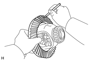
Coat 3 or 4 teeth at 3 different positions on the ring gear with Prussian blue.
Install the differential case and differential case bearing retainer.
- Torque:
- 50 N*m (510 kgf*cm, 37 ft.*lbf)
Hold the companion flange firmly in place and rotate the ring gear in both directions.
Remove the differential case bearing retainer and differential case.
Inspect the tooth contact pattern.
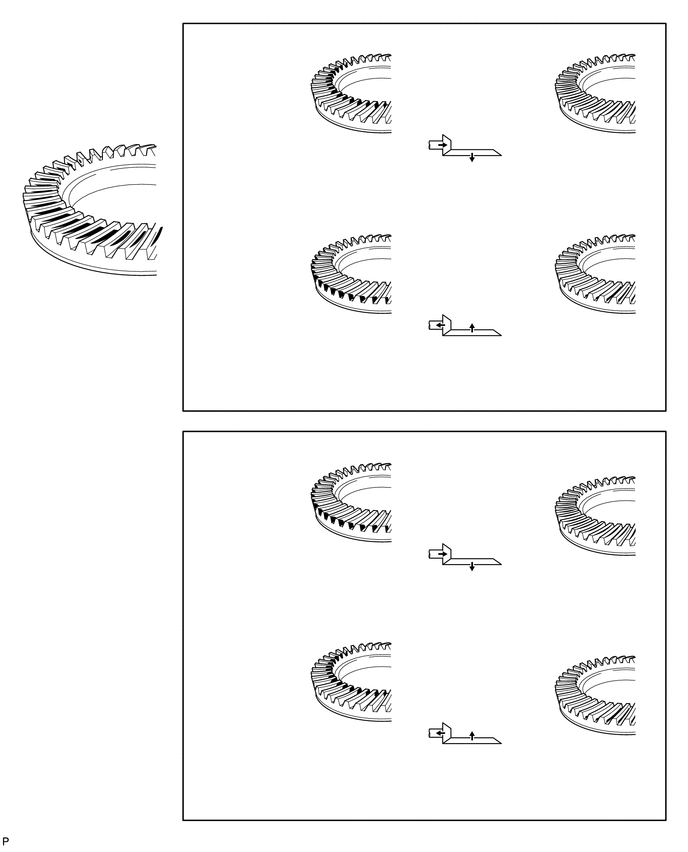
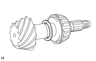
| *1 | Drive Pinion Water |
If the teeth are not contacting properly, use the following chart to select a proper washer.
- Standard Washer Thickness:
Thickness mm (in.) Thickness mm (in.) Thickness mm (in.) 1.69 to 1.71 (0.0666 to 0.0673) 1.93 to 1.95 (0.0760 to 0.0767) 2.17 to 2.19 (0.0855 to 0.0862) 1.72 to 1.74 (0.0678 to 0.0685) 1.96 to 1.98 (0.0772 to 0.0779) 2.20 to 2.22 (0.0867 to 0.0874) 1.75 to 1.77 (0.0689 to 0.0696) 1.99 to 2.01 (0.0784 to 0.0791) 2.23 to 2.25 (0.0878 to 0.0885) 1.78 to 1.80 (0.0701 to 0.0708) 2.02 to 2.04 (0.0796 to 0.0803) 2.26 to 2.28 (0.0890 to 0.0897) 1.81 to 1.83 (0.0713 to 0.0720) 2.05 to 2.07 (0.0807 to 0.0814) 2.29 to 2.31 (0.0902 to 0.0909) 1.84 to 1.86 (0.0725 to 0.0732) 2.08 to 2.10 (0.0819 to 0.0826) 2.32 to 2.34 (0.0914 to 0.0921) 1.87 to 1.89 (0.0737 to 0.0744) 2.11 to 2.13 (0.0831 to 0.0838) - 1.90 to 1.92 (0.0748 to 0.0755) 2.14 to 2.16 (0.0843 to 0.0850) -
17.REMOVE FRONT DRIVE PINION COMPANION FLANGE NUT
18.REMOVE FRONT DRIVE PINION COMPANION FLANGE SUB-ASSEMBLY WITH DUST DEFLECTOR
19.REMOVE FRONT DIFFERENTIAL DRIVE PINION OIL SLINGER
20.REMOVE FRONT DRIVE PINION REAR TAPERED ROLLER BEARING
21.REMOVE DIFFERENTIAL DRIVE PINION
22.INSTALL FRONT DIFFERENTIAL DRIVE PINION BEARING SPACER
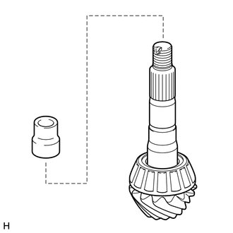
Install a new bearing spacer to the drive pinion.
23.INSTALL DIFFERENTIAL DRIVE PINION
24.INSTALL FRONT DRIVE PINION REAR TAPERED ROLLER BEARING
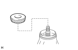
Install the roller bearing to the drive pinion.
25.INSTALL FRONT DIFFERENTIAL DRIVE PINION OIL SLINGER
26.INSTALL FRONT DIFFERENTIAL CARRIER OIL SEAL
27.INSTALL FRONT DRIVE PINION COMPANION FLANGE SUB-ASSEMBLY WITH DUST DEFLECTOR
28.INSTALL DIFFERENTIAL SIDE BEARING RETAINER
Remove any old seal packing material from the side bearing retainer.
- NOTICE:
-
Do not drop oil on the contact surfaces of the differential carrier and side bearing retainer.
Clean residual seal packing material on the contact surface using gasoline or alcohol.
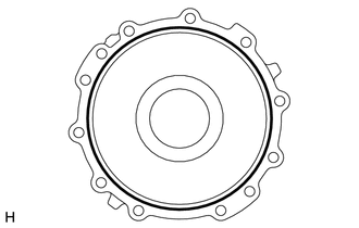
| *1 | Seal Packing |
Apply seal packing to the side bearing retainer as shown in the illustration.
- Seal packing:
Toyota Genuine seal packing 1281, Three Bond 1281 or equivalent
- HINT:
-
Install the side bearing retainer within 3 minutes after applying seal packing.
Install the side bearing retainer with the 10 bolts.
- Torque:
- 50 N*m (510 kgf*cm, 37 ft.*lbf)
29.INSPECT TOTAL PRELOAD
Using a torque wrench, measure the preload with the teeth of the drive pinion and ring gear in contact.
- Standard Preload (Starting Torque):
Item Specified Condition New bearing 1.0 to 1.5 N*m (11 to 15 kgf*cm, 9 to 13 in.*lbf) + ring gear preload Reused bearing 0.5 to 0.7 N*m (6 to 7 kgf*cm, 5 to 6 in.*lbf) + ring gear preload
If necessary, disassemble and inspect the differential.
30.INSPECT DIFFERENTIAL RING GEAR AND DIFFERENTIAL DRIVE PINION BACKLASH
Using SST and a dial indicator, measure the ring gear backlash.
- SST
- 09564-32011
- Standard backlash:
0.11 to 0.21 mm (0.00433 to 0.00826 in.)
If the backlash is not within the specification, adjust the side bearing preload.
31.INSPECT FRONT DRIVE PINION COMPANION FLANGE SUB-ASSEMBLY
32.STAKE DRIVE PINION NUT
33.INSTALL DIFFERENTIAL SIDE GEAR SHAFT OIL SEAL LH
34.INSTALL FRONT DIFFERENTIAL SIDE BEARING RETAINER DEFLECTOR
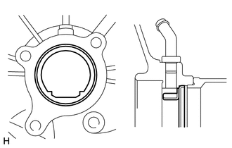
Using a brass bar and hammer, tap in the side bearing retainer deflector.
- NOTICE:
-
Make sure to install the side bearing retainer deflector in the correct direction.
35.INSTALL DIFFERENTIAL SIDE GEAR INTER SHAFT SUB-ASSEMBLY
Install a new snap ring to the side gear inter shaft.
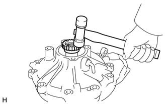
Using a plastic-faced hammer, tap the side gear inter shaft into the differential case.
Check that there is 2 to 3 mm (0.0788 to 0.118 in.) of axial play.
Check that the side gear inter shaft cannot be completely pulled out by hand.
36.INSTALL DIFFERENTIAL CLUTCH SLEEVE
Install the differential clutch sleeve.
37.INSTALL FRONT DIFFERENTIAL TUBE ASSEMBLY
Remove any old seal packing material on the contact surfaces of the differential and clutch case.
- NOTICE:
-
Do not drop oil on the contact surfaces of the differential and clutch case.
Clean residual seal packing material on the contact surface using gasoline or alcohol.
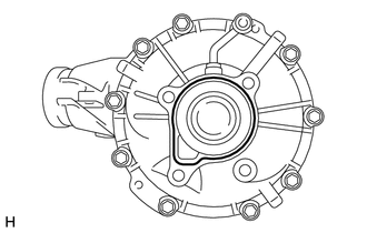
| *1 | Seal Packing |
Apply seal packing to the differential as shown in the illustration.
- Seal packing:
Toyota Genuine seal packing 1281, Three Bond 1281 or equivalent
- HINT:
-
Install the differential tube within 3 minutes after applying seal packing.
Install the differential tube to the differential.
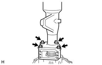
Clean the threads of the 4 bolts and retainer bolt holes with toluene or trichloroethylene.
Install the 4 bolts.
- Torque:
- 110 N*m (1122 kgf*cm, 81 ft.*lbf)
38.INSTALL DIFFERENTIAL VACUUM ACTUATOR ASSEMBLY
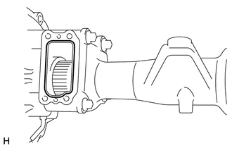
Remove any seal packing material from the contact surface of the differential and clutch case. Also, do not drop oil on the contact surfaces.
Clean residual seal packing material from the contact surfaces using gasoline or alcohol.
Apply seal packing to the differential tube as shown.
- Seal packing:
Toyota Genuine seal packing 1281, Three Bond 1281 or equivalent
- HINT:
-
Install the actuator within 3 minutes after applying seal packing.
Clean the threads of the 4 bolts and retainer bolt holes with toluene or trichloroethylene.
Install the actuator to the differential tube.
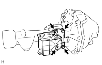
Install the 4 bolts.
- Torque:
- 21 N*m (210 kgf*cm, 15 ft.*lbf)