BRAKE SYSTEM (OTHER) BRAKE PEDAL(w/o VSC) INSTALLATION
PROCEDURE

 1.INSTALL BRAKE PEDAL SUPPORT SUB-ASSEMBLY
Install the support with the 4 nuts.
- Torque:
- 14 N*m (145 kgf*cm, 10 ft.*lbf)
for 1K-FTV and 2KD-FTV with Manual Transmission:
Attach the connector clamp and clamp to the brake pedal support sub-assembly.
Install the bolt to the support.
- Torque:
- 18 N*m (184 kgf*cm, 13 ft.*lbf)
2.CONNECT BRAKE MASTER CYLINDER PUSH ROD CLEVIS
Apply a light coat of lithium soap base glycol grease to the clevis pin.
Connect the push rod clevis to the brake pedal.
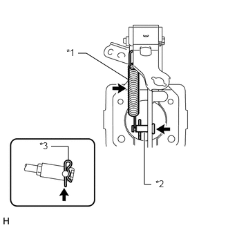
| *1 | Brake Pedal Return Spring |
| *2 | Clevis Pin |
| *3 | Clip |
Install the clevis pin and clip.
- NOTICE:
-
The clip must be installed as shown in the illustration.
Install the return spring.
Connect the stop light switch connector.
3.CHECK AND ADJUST BRAKE PEDAL HEIGHT
4.INSTALL UPPER INSTRUMENT PANEL SUB-ASSEMBLY
5.CONNECT CABLE TO NEGATIVE BATTERY TERMINAL
- NOTICE:
-
When disconnecting the cable, some systems need to be initialized after the cable is reconnected (See page General>INTRODUCTION>REPAIR INSTRUCTION>INITIALIZATION).