LIGHTING (EXT) RELAY ON-VEHICLE INSPECTION
PROCEDURE

 1.REMOVE HEADLIGHT RELAY
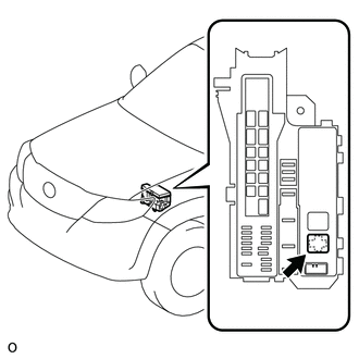
Remove the headlight relay from the engine room relay box.
2.INSPECT HEADLIGHT RELAY
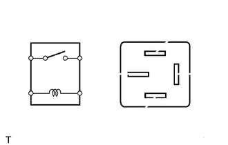
Measure the resistance according to the value(s) in the table below.
- Standard Resistance:
Tester Connection Condition Specified Condition 3 - 5 Battery voltage not applied to terminals 1 and 2 10 kΩ or higher Battery voltage applied to terminals 1 and 2 Below 1 Ω
If the result is not as specified, replace the headlight relay.
3.INSTALL HEADLIGHT RELAY
Install the headlight relay to the engine room relay box.
4.REMOVE TAILLIGHT RELAY
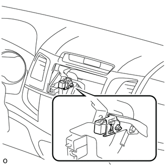
Remove the center instrument cluster finish panel assembly (See page Vehicle Interior>INTERIOR PANELS / TRIM>UPPER INSTRUMENT PANEL>REMOVAL).
Remove the radio receiver assembly (See page Vehicle Interior>INTERIOR PANELS / TRIM>UPPER INSTRUMENT PANEL>REMOVAL).
Remove the taillight relay.
5.INSPECT TAILLIGHT RELAY
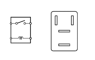
Measure the resistance according to the value(s) in the table below.
- Standard Resistance:
Tester Connection Condition Specified Condition 3 - 5 Battery voltage not applied to terminals 1 and 2 10 kΩ or higher Battery voltage applied to terminals 1 and 2 Below 1 Ω
If the result is not as specified, replace the taillight relay.
6.INSTALL TAILLIGHT RELAY
Install the taillight relay.
Install the radio receiver assembly (See page Vehicle Interior>INTERIOR PANELS / TRIM>UPPER INSTRUMENT PANEL>INSTALLATION).
Install the center instrument cluster finish panel assembly (See page Vehicle Interior>INTERIOR PANELS / TRIM>UPPER INSTRUMENT PANEL>INSTALLATION).