2TR-FBE ENGINE CONTROL SFI SYSTEM Sub Tank Fuel Pump Control Circuit
DESCRIPTION
A Flexible Fuel Vehicle (FFV) is a vehicle with an engine that can be used with a high concentration of ethyl alcohol fuel.
This FFV uses a sub tank system, which allows fuel (with a gasoline concentration of 78% or more) to be injected to the fuel delivery spacer from the sub tank when the ambient temperature is low to enhance low-temperature startability.
The fuel volume is controlled by the ECM and varies depending on the duty ratio of the fuel injection volume control solenoid valve assembly.
If the fuel injection volume control solenoid valve assembly is stuck open, the fuel cut solenoid valve assembly will operate and cut the fuel flow based on signals from the ECM, preventing the fuel from being drawn out of the sub tank due to vacuum from the engine.
WIRING DIAGRAM
Refer to DTC P1001 (See page Engine / Hybrid System>2TR-FBE ENGINE CONTROL>SFI SYSTEM>P1001).
CAUTION / NOTICE / HINT
- NOTICE:
-
Inspect the fuses for circuits related to this system before performing the following inspection procedure.
PROCEDURE
Connect the intelligent tester to the DLC3.
Turn the ignition switch to ON.
Turn the tester on.
Enter the following menus: Powertrain / Engine and ECT / Active Test / Sub Fuel Tank VSV.
- Powertrain > Engine and ECT > Active Test
-
Tester Display Sub Fuel Tank VSV - 50004 234 163
Check whether the sub tank fuel pump operation sound occurs when performing the Active Test on the tester.
- HINT:
-
The test is possible only once because the engine may be damaged if sub tank fuel flows into the cylinders.
- OK:
Sub tank fuel pump operating sound occurs.
- Result:
Condition Proceed to NG A OK
(When troubleshooting according to Problem Symptoms Table)B OK
(When troubleshooting according to DTC chart)C
A
B
C
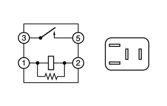
Remove the FFV relay from the engine room relay block.
Measure the resistance according to the value(s) in the table below.
- Standard Resistance:
Tester Connection Condition Specified Condition 3 - 5 Battery voltage is not applied between terminals 1 and 2 10 kΩ or higher 3 - 5 Battery voltage is applied between terminals 1 and 2 Below 1 Ω
Reinstall the FFV relay.
- Result:
Proceed to OK NG
OK
NG
Remove the FFV relay from the engine room relay block.
Remove the IGN fuse from the instrument panel junction block.
Measure the resistance according to the value(s) in the table below.
- Standard Resistance (Check for Open):
Tester Connection Condition Specified Condition FFV relay terminal (2) - IGN fuse terminal (2) Always Below 1 Ω
Reinstall the IGN fuse.
Reinstall the FFV relay.
- Result:
Proceed to OK NG
OK
NG
Remove the FFV relay from the engine room relay block.
Remove the integration relay from the engine room relay block.
Disconnect the integration relay connector.
Measure the resistance according to the value(s) in the table below.
- Standard Resistance (Check for Open):
Tester Connection Condition Specified Condition FFV relay terminal (5) - 1J-5 Always Below 1 Ω
- Standard Resistance (Check for Short):
Tester Connection Condition Specified Condition FFV relay terminal (5) or 1J-5 - Body ground Always 10 kΩ or higher
Reinstall the FFV relay.
Reconnect the integration relay connector.
Reinstall the integration relay.
- Result:
Proceed to OK NG
OK
NG
Disconnect the ECM connector.
Remove the FFV relay from the engine room relay block.
Measure the resistance according to the value(s) in the table below.
- Standard Resistance (Check for Open):
Tester Connection Condition Specified Condition G146-11 (FFR) - FFV relay terminal (1) Always Below 1 Ω
- Standard Resistance (Check for Short):
Tester Connection Condition Specified Condition G146-11 (FFR) or FFV relay terminal (1) - Body ground Always 10 kΩ or higher
Reinstall the FFV relay.
Reconnect the ECM connector.
- Result:
Proceed to OK NG
OK
NG
Remove the FFV relay from the engine room relay block.
Disconnect the fuel pump (for fuel sub tank) connector.
Measure the resistance according to the value(s) in the table below.
- Standard Resistance (Check for Open):
Tester Connection Condition Specified Condition FFV relay terminal (3) - A71-2 Always Below 1 Ω
- Standard Resistance (Check for Short):
Tester Connection Condition Specified Condition FFV relay terminal (3) or A71-2 - Body ground Always 10 kΩ or higher
Reconnect the fuel pump (for fuel sub tank) connector.
Reinstall the FFV relay.
- Result:
Proceed to OK NG
OK
NG
Inspect the fuel pump (for fuel sub tank).
Click hereEngine / Hybrid System>2TR-FBE FUEL>FUEL PUMP(for Fuel Sub Tank)>INSPECTION
- Result:
Proceed to OK NG
OK
NG
Disconnect the fuel pump (for fuel sub tank) connector.
Measure the resistance according to the value(s) in the table below.
- Standard Resistance (Check for Open):
Tester Connection Condition Specified Condition A71-1 - Body ground Always Below 1 Ω
Reconnect the fuel pump (for fuel sub tank) connector.
- Result:
Proceed to OK NG
OK
NG
Disconnect the ECM connector.
Measure the resistance according to the value(s) in the table below.
- Standard Resistance (Check for Open):
Tester Connection Condition Specified Condition C98-11 (E01) - Body ground Always Below 1 Ω
Reconnect the ECM connector.
- Result:
Proceed to OK NG
OK
NG