BRAKE CONTROL / DYNAMIC CONTROL SYSTEMS VEHICLE STABILITY CONTROL SYSTEM C1268 Transfer L4 Position Switch Circuit
DESCRIPTION
| DTC No. | Detection Item | DTC Detection Condition | Trouble Area |
|---|---|---|---|
| C1268 | Transfer L4 Position Switch Circuit | No signal is input to the EXI4 terminal of the skid control ECU. | ·
L4 position switch (No. 1 transfer indicator switch) ·
L4 position switch circuit ·
Skid control ECU (Brake actuator assembly) ·
Transmission control ECU assembly (for Automatic Transmission) |
*C1268: for 4WD
WIRING DIAGRAM
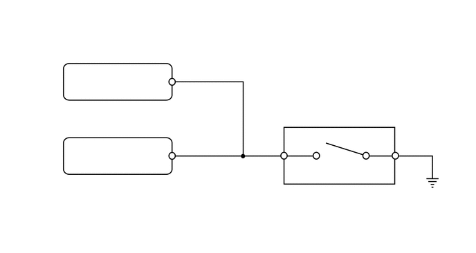
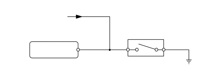
CAUTION / NOTICE / HINT
- NOTICE:
- ·
After replacing the brake actuator assembly, perform calibration (See page Brake>BRAKE CONTROL / DYNAMIC CONTROL SYSTEMS>VEHICLE STABILITY CONTROL SYSTEM>CALIBRATION).
·Before disconnecting the connector, make sure that there are no problems with the connection.
·After disconnecting the connector, make sure that the connector case and terminals are not deformed or corroded.
PROCEDURE
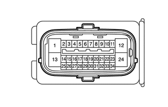
| *a | Front view of wire harness connector
(to Skid Control ECU [Brake Actuator Assembly]) |
Connect the skid control ECU (brake actuator assembly) connector.
Set the vehicle to the L4 state using the transfer shift lever.
Disconnect the skid control ECU (brake actuator assembly) connector.
Measure the voltage according to the value(s) in the table below.
- Standard Voltage:
Tester Connection Condition Specified Condition A36-9 (EXI4) - Body ground ·Ignition switch ON
·Transfer shift position L4
Below 1.5 V
Connect the skid control ECU (brake actuator assembly) connector.
Set the vehicle to the H4 or H2 state using the transfer shift lever.
Disconnect the skid control ECU (brake actuator assembly) connector.
Measure the voltage according to the value(s) in the table below.
- Standard Voltage:
Tester Connection Condition Specified Condition A36-9 (EXI4) - Body ground ·Ignition switch ON
·Transfer shift position not L4
11 to 14 V
- Result:
Proceed to OK NG
OK
NG
Clear the DTC.
Click hereBrake>BRAKE CONTROL / DYNAMIC CONTROL SYSTEMS>VEHICLE STABILITY CONTROL SYSTEM>DTC CHECK / CLEAR
- Chassis > ABS/VSC/TRC > Clear DTCs
- 50002 105
Turn the ignition switch off.
Check if the same DTC is output.
Click hereBrake>BRAKE CONTROL / DYNAMIC CONTROL SYSTEMS>VEHICLE STABILITY CONTROL SYSTEM>DTC CHECK / CLEAR
- Chassis > ABS/VSC/TRC > Trouble Codes
- 50001 105
- Result:
Result Proceed to DTC is output A DTC is not output B
A
B
Click hereGeneral>INTRODUCTION>HOW TO TROUBLESHOOT ECU CONTROLLED SYSTEMS>HOW TO PROCEED WITH TROUBLESHOOTING
Turn the ignition switch off.
Disconnect the skid control ECU (brake actuator assembly) connector.
for Automatic Transmission: Disconnect the G40 transmission control ECU connector.
Disconnect the L4 position switch (No. 1 transfer indicator switch) connector.
Measure the resistance according to the value(s) in the table below.
- Standard Resistance:
Tester Connection Condition Specified Condition A36-9 (EXI4) - C29-1 Always Below 1 Ω A36-9 (EXI4) - Body ground Always 10 kΩ or higher C29-2 - Body ground Always Below 1 Ω
- Result:
Proceed to OK NG
OK
NG
Turn the ignition switch off.
Remove the L4 position switch (No. 1 transfer indicator switch).
Click hereDrivetrain>VF2A TRANSFER / 4WD / AWD>TRANSFER INDICATOR SWITCH>REMOVAL
Inspect the L4 position switch (No. 1 transfer indicator switch).
Click hereDrivetrain>VF2A TRANSFER / 4WD / AWD>TRANSFER INDICATOR SWITCH>INSPECTION
- Result:
Proceed to OK NG
OK
NG
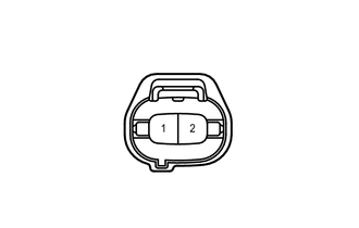
| *a | Front view of wire harness connector
(to L4 Position Switch [No. 1 Transfer Indicator Switch]) |
Turn the ignition switch off.
Disconnect the L4 position switch (No. 1 transfer indicator switch) connector.
Disconnect the skid control ECU (brake actuator assembly) connector.
for Automatic Transmission: Connect the transmission control ECU connector.
Measure the voltage according to the value(s) in the table below.
- Standard Voltage:
Tester Connection Switch Condition Specified Condition 1 - 2 Ignition switch ON 11 to 14 V
- Result:
Result Proceed to OK A NG (for Manual Transmission) B NG (for Automatic Transmission) C
A
Click hereGeneral>INTRODUCTION>HOW TO TROUBLESHOOT ECU CONTROLLED SYSTEMS>HOW TO PROCEED WITH TROUBLESHOOTING
B
C
Turn the ignition switch off.
Disconnect the skid control ECU (brake actuator assembly) connector.
Disconnect the G40 transmission control ECU connector.
Disconnect the L4 position switch (No. 1 transfer indicator switch) connector.
Measure the resistance according to the value(s) in the table below.
- Standard Resistance:
Tester Connection Condition Specified Condition A36-9 (EXI4) - G40-15 (L4) Always Below 1 Ω A36-9 (EXI4) - Body ground Always 10 kΩ or higher
- Result:
Proceed to OK NG
OK
NG