 |
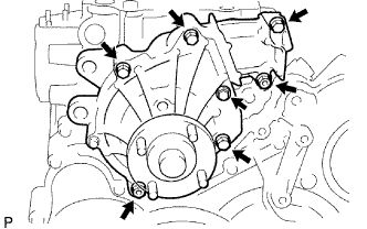
Install a new gasket and the water pump with the 5 bolts and 2 nuts.
- Torque:
- 13 N*m{ 133 kgf*cm , 10 ft.*lbf }
WATER PUMP (w/o Glow Plug Controller) > INSTALLATION |
| 1. INSTALL WATER PUMP ASSEMBLY |
|
Install a new gasket and the water pump with the 5 bolts and 2 nuts.
| 2. INSTALL NO. 2 TIMING BELT COVER |
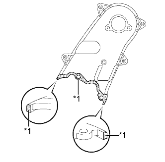 |
Apply seal packing (FIPG) to the specified areas shown in the illustration.
| *1 | Seal Packing |
Clean the bolts and their holes.
Apply adhesive to 2 or 3 threads at the end of each of the 4 bolts.
Install the No. 2 timing belt cover with the 4 bolts and nut.
| 3. INSTALL CAMSHAFT TIMING PULLEY |
Install the camshaft timing pulley.
Install the bolt of the camshaft timing pulley while holding the camshaft with a wrench.
| 4. INSTALL TIMING BELT |
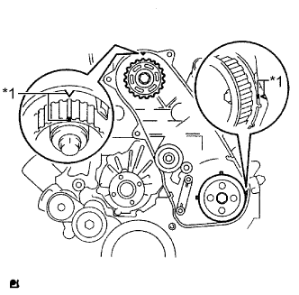 |
Check that the timing marks are aligned as shown in the illustration.
| *1 | Timing Mark |
Install the timing belt to the pump drive shaft pulley, camshaft timing pulley and No. 1 timing belt idler in sequence.
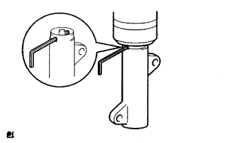 |
Place the tensioner upright. Then set a press on the top of the tensioner.
Using the press, slowly push in the push rod using 981 to 9800 N (100 to 999 kgf, 220 to 2203 lbf) of force.
Align the holes of the push rod and housing. Then pass a 1.5 mm hexagon wrench through the holes to fix the push rod in place.
Temporarily install the timing belt tensioner with the 2 bolts while pushing the idler pulley toward the timing belt.
Tighten the 2 bolts.
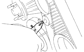 |
Remove the 1.5 mm hexagon wrench from the tensioner.
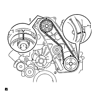 |
Turn the crankshaft clockwise 720° and check that the timing marks are aligned as shown in the illustration.
| *1 | Timing Mark |
| 5. INSTALL NO. 1 TIMING BELT IDLER SUB-ASSEMBLY |
| 6. INSTALL CYLINDER HEAD COVER SUB-ASSEMBLY |
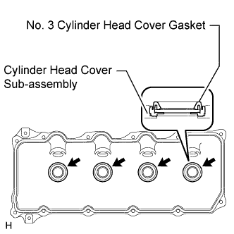 |
Install 4 new No. 3 cylinder head cover gaskets to the cylinder head cover in the directions shown in the illustration.
Remove any old seal packing (FIPG material) from the cylinder head.
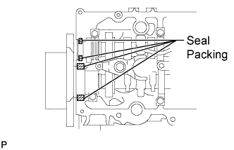 |
Apply seal packing to the specific areas shown in the illustration.
Install a new cylinder head cover gasket and the cylinder head cover with the 10 bolts and 2 nuts.
Install 4 new nozzle holder seals.
Connect the ventilation hose.
Connect the 4 connectors and install the 3 bolts.
| 7. INSTALL INJECTION PIPE |
Temporarily install the No. 1, No. 2 and No. 3 injection pipes with the union nuts.
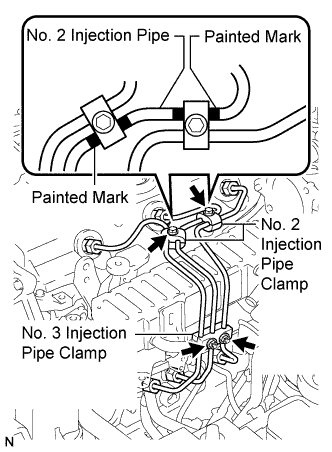 |
w/ EGR Cooler:
Install the No. 2 and No. 3 injection pipe clamps with the 2 bolts and 2 nuts as shown in the illustration.
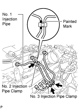 |
w/o EGR Cooler:
Install the No. 2 and No. 3 injection pipe clamps with the bolt and 2 nuts as shown in the illustration.
Using a 17 mm union nut wrench, tighten the injection pipe union nuts on the common rail side.
Using a 17 mm union nut wrench, tighten the injection pipe union nuts on the injector side.
| 8. INSTALL NO. 1 TIMING BELT COVER |
Install the timing belt cover and 6 washers with the 6 bolts.
| 9. INSTALL CHARGE AIR COOLER ASSEMBLY |
Install the CAC (Click here).
| 10. INSTALL V-RIBBED BELT TENSIONER ASSEMBLY |
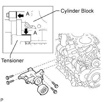 |
Install the tensioner with the 4 bolts.
| 11. INSTALL GENERATOR ASSEMBLY |
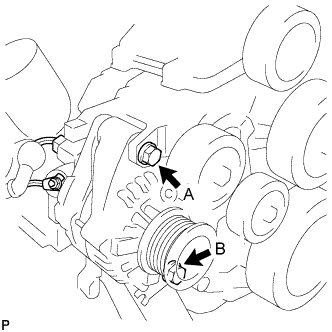 |
Install the generator and with the 2 bolts.
Install the generator wire with the nut.
Connect the generator connector.
| 12. INSTALL COOLER COMPRESSOR ASSEMBLY |
Install the compressor with the 4 bolts.
| 13. INSTALL FAN SHROUD |
Install the fan pulley to the water pump.
Install the shroud together with the coupling fan between the radiator and engine component.
Install the fluid coupling fan to the water pump with the 4 nuts.
Tighten the nuts as much as possible by hand.
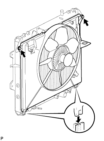 |
Attach the shroud's claws to the radiator.
Install the shroud with the 2 bolts.
Install the drive belt .
Tighten the 4 nuts of the fluid coupling fan.
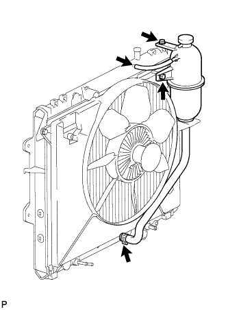 |
Install the radiator reservoir with the 2 bolts.
Connect the No. 1 and No. 2 water by-pass hoses to the tank upper and lower.
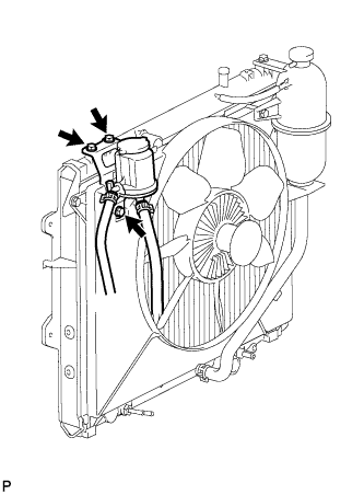 |
Install the oil reservoir with the 3 bolts.
| 14. CONNECT RADIATOR HOSE INLET |
| 15. ADD ENGINE COOLANT |
Tighten the radiator drain cock plug by hand.
Tighten the cylinder block drain cock plug.
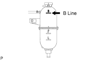 |
Fill the radiator with TOYOTA Super Long Life Coolant (SLLC) to the reservoir tank's B line.
| Item | Specified Condition |
| A/T | 11.1 liters (11.7 US qts, 9.8 Imp. qts) |
| M/T | 9.8 liters (10.4 US qts, 8.6 Imp. qts) |
Press the inlet and outlet radiator hoses several times by hand, and then check the level of the coolant.
If the coolant level drops below the B line, add TOYOTA SLLC to the B line.
Install the radiator reservoir cap.
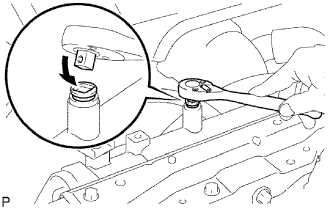 |
Using a wrench, install the vent plug.
Bleed air from the cooling system.
Warm up the engine until the thermostat opens. While the thermostat is open, circulate the coolant for several minutes.
Maintain the engine speed at 2,500 to 3,000 rpm.
Press the inlet and outlet radiator hoses several times by hand to bleed air.
Stop the engine and wait until the coolant cools down to ambient temperature.
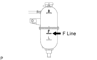 |
After the coolant cools down, check that the coolant level is at the F line.
If the coolant level is below the F line, add TOYOTA SLLC to the F line.
| 16. CONNECT CABLE TO NEGATIVE BATTERY TERMINAL |
| 17. CHECK FOR ENGINE COOLANT LEAKS |
Check for coolant leaks (Click here).
| 18. CHECK FOR ENGINE OIL LEAKS |
| 19. INSTALL NO. 1 ENGINE UNDER COVER |
| 20. PERFORM INITIALIZATION |
Perform initialization (Click here).