| A |  |
| GO TO INTERNAL EEPROM MALFUNCTION CIRCUIT (Click here) |
| B | |
| GO TO FUEL PRESSURE SENSOR CIRCUIT (Click here) |
DTC P13C1 Fuel Temperature Sensor Circuit Low #1 |
DTC P13C2 Fuel Temperature Sensor Circuit High #1 |
DTC P13C3 Fuel Temperature Sensor Circuit Range/Performance #1 |
DTC P13C6 Fuel Temperature Sensor Circuit Low #2 |
DTC P13C7 Fuel Temperature Sensor Circuit High #2 |
DTC P13C8 Fuel Temperature Sensor Circuit Range/Performance #2 |
DTC P13CB Fuel Temperature Sensor Circuit Low #3 |
DTC P13CC Fuel Temperature Sensor Circuit High #3 |
DTC P13CD Fuel Temperature Sensor Circuit Range/Performance #3 |
DTC P13D1 Fuel Temperature Sensor Circuit Low #4 |
DTC P13D2 Fuel Temperature Sensor Circuit High #4 |
DTC P13D3 Fuel Temperature Sensor Circuit Range/Performance #4 |
| DTC Detection Drive Pattern | DTC Detection Condition | Trouble Area |
| Ignition switch ON for 8 seconds or more | The voltage value (communication result) from the fuel temperature sensor is 1.75 V or less for 3 seconds or more (1 trip detection logic) |
|
| DTC Detection Drive Pattern | DTC Detection Condition | Trouble Area |
| Ignition switch ON for 8 seconds or more | The voltage value (communication result) from the fuel temperature sensor is 3.34 V or more for 3 seconds or more (1 trip detection logic) |
|
| DTC Detection Drive Pattern | DTC Detection Condition | Trouble Area |
| Ignition switch ON for 8 seconds or more | The voltage value (communication result) from the fuel temperature sensor differs by 23.6°C or more compared to other cylinders for 3 seconds or more (1 trip detection logic) |
|
| DTC No. | Data List |
| P13C1 P13C2 P13C6 P13C7 P13CB P13CC P13D1 P13D2 | Fuel Temperature #1 Fuel Temperature #2 Fuel Temperature #3 Fuel Temperature #4 |
| P13C3 P13C8 P13CD P13D3 |
| Temperature Displayed | Malfunction |
| -40°C (-40°F) | Open circuit |
| 140°C (284°F) or higher | Short circuit |
| 1.CHECK ANY OTHER DTCS OUTPUT |
Connect the GTS to the DLC3.
Turn the ignition switch to ON and turn the GTS on.
Enter the following menus: Powertrain / Engine / Trouble Codes.
Read the DTCs
| Result | Proceed to |
| "Fuel pressure sensor circuit DTC" and "Injector Internal EEPROM Malfunction circuit DTC" are output*1 | A |
| "Fuel pressure sensor circuit DTC" and "Fuel temperature sensor circuit" are output*2 | B |
| Only DTCs related to the fuel temperature sensor circuit are output*3 | C |
|
| ||||
|
| ||||
| C | |
 |
| 2.CHECK ECM (FUEL TEMPERATURE SENSOR VOLTAGE) |
Disconnect the fuel pressure sensor connector.
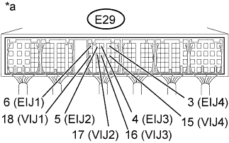 |
Measure the voltage according to the value(s) in the table below.
| *a | Component with harness connected (ECM) |
| Tester Connection | Switch Condition | Specified Condition |
| E29-18 (VIJ1) - E29-6 (EIJ1) | Ignition switch ON | 4.5 to 5.5 V |
| E29-17 (VIJ2) - E29-5 (EIJ2) | Ignition switch ON | 4.5 to 5.5 V |
| E29-16 (VIJ3) - E29-4 (EIJ3) | Ignition switch ON | 4.5 to 5.5 V |
| E29-15 (VIJ4) - E29-3 (EIJ4) | Ignition switch ON | 4.5 to 5.5 V |
|
| ||||
| OK | |
|
| 3.CHECK HARNESS AND CONNECTOR (INJECTOR ASSEMBLY - ECM) |
Disconnect the injector assembly connector.
Disconnect the ECM connector.
Measure the resistance according to the value(s) in the table below.
| Tester Connection | Condition | Specified Condition |
| F31-2 (VIJ1) - E29-18 (VIJ1) | Always | Below 1 Ω |
| F31-1 (EIJ1) - E29-6 (EIJ1) | Always | Below 1 Ω |
| F32-2 (VIJ2) - E29-17 (VIJ2) | Always | Below 1 Ω |
| F32-1 (EIJ2) - E29-5 (EIJ2) | Always | Below 1 Ω |
| F33-2 (VIJ3) - E29-16 (VIJ3) | Always | Below 1 Ω |
| F33-1 (EIJ3) - E29-4 (EIJ3) | Always | Below 1 Ω |
| F34-2 (VIJ4) - E29-15 (VIJ4) | Always | Below 1 Ω |
| F34-1 (EIJ4) - E29-3 (EIJ4) | Always | Below 1 Ω |
| F31-2 (VIJ1) or E29-18 (VIJ1) - Body ground | Always | 10 kΩ or higher |
| F31-1 (EIJ1) or E29-6 (EIJ1) - Body ground | Always | 10 kΩ or higher |
| F32-2 (VIJ2) or E29-17 (VIJ2) - Body ground | Always | 10 kΩ or higher |
| F32-1 (EIJ2) or E29-5 (EIJ2) - Body ground | Always | 10 kΩ or higher |
| F33-2 (VIJ3) or E29-16 (VIJ3) - Body ground | Always | 10 kΩ or higher |
| F33-1 (EIJ3) or E29-4 (EIJ3) - Body ground | Always | 10 kΩ or higher |
| F34-2 (VIJ4) or E29-15 (VIJ4) - Body ground | Always | 10 kΩ or higher |
| F34-1 (EIJ4) or E29-3 (EIJ4) - Body ground | Always | 10 kΩ or higher |
Reconnect the injector assembly connector.
Reconnect the ECM connector.
|
| ||||
| OK | |
|
| 4.REPLACE INJECTOR ASSEMBLY (RELEVANT CYLINDER) |
Replace the injector assembly of the cylinder relevant to the DTC (Click here).
| NEXT | |
|
| 5.BLEED AIR FROM FUEL SYSTEM |
Bleed the air from the fuel system .
|
| ||||
| 6.REPLACE ECM |
Replace the ECM (Click here).
|
| ||||
| 7.REPAIR OR REPLACE HARNESS OR CONNECTOR |
Repair or replace the harness or connector.
| NEXT | |
|
| 8.CONFIRM WHETHER MALFUNCTION HAS BEEN SUCCESSFULLY REPAIRED |
Connect the GTS to the DLC3.
Clear the DTCs (Click here).
Turn the ignition switch off for 30 seconds or more.
Turn the ignition switch to ON for 8 seconds or more.
Enter the following menus: Powertrain / Engine / Trouble Codes.
Confirm that the DTC is not output again.
| NEXT | ||
 | ||
| ||
