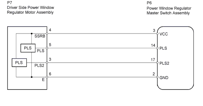
POWER WINDOW CONTROL SYSTEM (w/ Jam Protection Function) > Auto Up / Down Function does not Operate |
| 1.CHECK MANUAL UP / DOWN FUNCTION (FOR DRIVER SIDE) |
Check that the manual UP / DOWN function operates normally.
|
| ||||
| OK | |
 |
| 2.RESET INITIALIZATION |
Initialize the driver side power window regulator motor assembly (Click here).
Check that the driver side door power window moves when the auto up and down functions of the power window regulator master switch assembly are operated (Click here).
|
| ||||
| OK | ||
 | ||
| ||
| 3.CHECK WIRE HARNESS (MASTER SWITCH - MOTOR (FOR DRIVER SIDE)) |
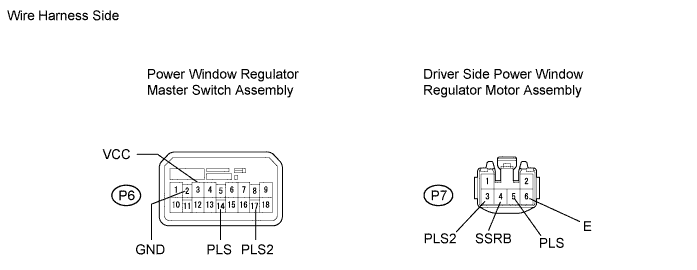
Disconnect the P6 master switch connector.
Disconnect the P7 motor connector.
Measure the resistance of the wire harness side connectors.
| Tester Connection | Specified Condition |
| P6-3 (VCC) - P7-4 (SSRB) | Below 1 Ω |
| P6-14 (PLS) - P7-5 (PLS) | Below 1 Ω |
| P6-17 (PLS2) - P7-3 (PLS2) | Below 1 Ω |
| P6-2 (GND) - P7-6 (E) | Below 1 Ω |
| P6-3 (VCC) or P7-4 (SSRB) - Body ground | 10 kΩ or higher |
| P6-14 (PLS) or P7-5 (PLS) - Body ground | 10 kΩ or higher |
| P6-17 (PLS2) or P7-3 (PLS2) - Body ground | 10 kΩ or higher |
|
| ||||
| OK | |
|
| 4.CHECK POWER WINDOW REGULATOR MASTER SWITCH ASSEMBLY (PLS, PLS2 SIGNAL) |
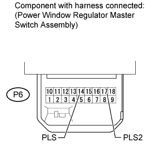 |
Remove the power window regulator master switch assembly with its connectors still connected.
Using an oscilloscope, check the waveform.
| Tester Connection | Switch Condition | Specified Condition |
| P6-14 (PLS) - Body ground | Ignition switch ON, driver side power window switch OFF → UP or DOWN | Pulse waveform is output |
| P6-17 (PLS2) - Body ground |
|
| ||||
| OK | ||
| ||
| ||

