| B |  |
| Go to step 8 |
| C | |
| Go to step 13 |
DTC P064C Glow Plug Control Module |
DTC P066B Cylinder 1 Glow Plug Control Circuit High |
DTC P066D Cylinder 2 Glow Plug Control Circuit High |
DTC P066F Cylinder 3 Glow Plug Control Circuit High |
DTC P0671 Cylinder 1 Glow Plug Circuit/Open |
DTC P0672 Cylinder 2 Glow Plug Circuit/Open |
DTC P0673 Cylinder 3 Glow Plug Circuit/Open |
DTC P0674 Cylinder 4 Glow Plug Circuit/Open |
DTC P067B Cylinder 4 Glow Plug Control Circuit High |
DTC P166F Glow Plug Control Module Circuit Short |
| DTC Detection Drive Pattern | DTC Detection Condition | Trouble Area |
| Enter check mode | The MOS inside the glow plug control unit is detected as being stuck on 3 times while the glow plugs are on (2 trip detection logic). | Glow plug controller |
| DTC Detection Drive Pattern | DTC Detection Condition | Trouble Area |
| Enter check mode | A short circuit in the No. 1 glow plug circuit is detected 3 times while the glow plugs are on (2 trip detection logic). |
|
| DTC Detection Drive Pattern | DTC Detection Condition | Trouble Area |
| Enter check mode | A short circuit in the No. 2 glow plug circuit is detected 3 times while the glow plugs are on (2 trip detection logic). |
|
| DTC Detection Drive Pattern | DTC Detection Condition | Trouble Area |
| Enter check mode | A short circuit in the No. 3 glow plug circuit is detected 3 times while the glow plugs are on (2 trip detection logic). |
|
| DTC Detection Drive Pattern | DTC Detection Condition | Trouble Area |
| Enter check mode | A short circuit in the No. 4 glow plug circuit is detected 3 times while the glow plugs are on (2 trip detection logic). |
|
| DTC Detection Drive Pattern | DTC Detection Condition | Trouble Area |
| Enter check mode | An open circuit in the No. 1 glow plug circuit is detected 3 times while the glow plugs are on (2 trip detection logic). |
|
| DTC Detection Drive Pattern | DTC Detection Condition | Trouble Area |
| Enter check mode | An open circuit in the No. 2 glow plug circuit is detected 3 times while the glow plugs are on (2 trip detection logic). |
|
| DTC Detection Drive Pattern | DTC Detection Condition | Trouble Area |
| Enter check mode | An open circuit in the No. 3 glow plug circuit is detected 3 times while the glow plugs are on (2 trip detection logic). |
|
| DTC Detection Drive Pattern | DTC Detection Condition | Trouble Area |
| Enter check mode | An open circuit in the No. 4 glow plug circuit is detected 3 times while the glow plugs are on (2 trip detection logic). |
|
| DTC Detection Drive Pattern | DTC Detection Condition | Trouble Area |
| Enter check mode | A short circuit in a wire harness between the glow plugs is detected 3 times while the glow plugs are on (2 trip detection logic). |
|
| 1.CHECK DTC OUTPUT |
Connect the GTS to the DLC3.
Turn the ignition switch to ON and turn the GTS on.
Enter the following menus: Powertrain / Engine / Trouble Codes.
Read the DTCs.
| Result | Proceed to |
| P0671, P0672, P0673 and/or P0674 is output | A |
| P066B, P066D, P066F and/or P067B is output | B |
| P064C and/or P166F is output | C |
|
| ||||
|
| ||||
| A | |
 |
| 2.CHECK GLOW PLUG CONTROLLER |
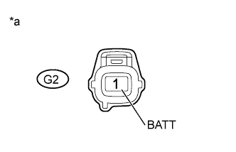 |
Disconnect the glow plug controller connector.
Measure the voltage according to the value(s) in the table below.
| Tester Connection | Condition | Specified Condition |
| G2-1 (BATT) - Body ground | Always | 11 to 14 V |
| *a | Front view of wire harness connector (to Glow Plug Controller) |
Reconnect the glow plug controller connector.
|
| ||||
| OK | |
|
| 3.CHECK HARNESS AND CONNECTOR |
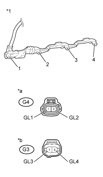 |
Disconnect connectors of the glow plug controller.
Remove the No. 1 glow plug connector from the glow plug.
Measure the resistance according to the value(s) in the table below.
| Tester Connection | Condition | Specified Condition |
| G4-1 (GL1) - No. 1 glow plug connector terminal 1 | Always | Below 1 Ω |
| G4-2 (GL2) - No. 1 glow plug connector terminal 2 | Always | Below 1 Ω |
| G3-1 (GL3) - No. 1 glow plug connector terminal 3 | Always | Below 1 Ω |
| G3-2 (GL4) - No. 1 glow plug connector terminal 4 | Always | Below 1 Ω |
| *1 | No. 1 Glow Plug Connector |
| *a | Front view of wire harness connector (to Glow Plug Controller) |
| *b | Front view of wire harness connector (to Glow Plug Controller) |
Reconnect the glow plug controller connector.
Reinstall the No. 1 glow plug connector.
|
| ||||
| OK | |
|
| 4.INSPECT GLOW PLUG |
Clear the DTCs (Click here).
Exchange the glow plugs of the malfunctioning cylinders (the cylinders indicated by output DTCs) with the glow plugs of normally functioning cylinders.
Turn the ignition switch to ON.
Turn the GTS on.
Using the GTS, switch the ECM from normal mode to check mode (Click here).
Read the DTCs.
| Result | Proceed to |
| Same DTCs (that have been erased) | A |
| Other DTCs | B |
|
| ||||
| B | |
|
| 5.REPLACE GLOW PLUG |
Replace the glow plug (Click here).
|
| ||||
| 6.REPAIR OR REPLACE HARNESS OR CONNECTOR |
Repair or replace the harness or connector.
| NEXT | |
|
| 7.CONFIRM WHETHER MALFUNCTION HAS BEEN SUCCESSFULLY REPAIRED |
Connect the GTS to the DLC3.
Clear the DTCs (Click here).
Turn the ignition switch off for 30 seconds or more.
Turn the ignition switch to ON.
Turn the GTS on.
Using the GTS, switch the ECM from normal mode to check mode (Click here).
Confirm that the DTC is not output again.
| NEXT | ||
 | ||
| ||
| 8.CHECK HARNESS AND CONNECTOR |
|
Disconnect connectors of the glow plug controller.
Remove the No. 1 glow plug connector from the glow plug.
Measure the resistance according to the value(s) in the table below.
| Tester Connection | Condition | Specified Condition |
| G4-1 (GL1) or No. 1 glow plug connector terminal 1 - Body ground | Always | 10 kΩ or higher |
| G4-2 (GL2) or No. 1 glow plug connector terminal 2 - Body ground | Always | 10 kΩ or higher |
| G3-1 (GL3) or No. 1 glow plug connector terminal 3 - Body ground | Always | 10 kΩ or higher |
| G3-2 (GL4) or No. 1 glow plug connector terminal 4 - Body ground | Always | 10 kΩ or higher |
| *1 | No. 1 Glow Plug Connector |
| *a | Front view of wire harness connector (to Glow Plug Controller) |
| *b | Front view of wire harness connector (to Glow Plug Controller) |
Reconnect the glow plug controller connector.
Reinstall the No. 1 glow plug connector.
|
| ||||
| OK | |
|
| 9.REPLACE GLOW PLUG CONTROLLER |
Replace the glow plug controller (Click here).
|
| ||||
| 10.REPAIR OR REPLACE HARNESS OR CONNECTOR |
Repair or replace the harness or connector.
| NEXT | |
|
| 11.CONFIRM WHETHER MALFUNCTION HAS BEEN SUCCESSFULLY REPAIRED |
Connect the GTS to the DLC3.
Clear the DTCs (Click here).
Turn the ignition switch off for 30 seconds or more.
Turn the ignition switch to ON.
Turn the GTS on.
Using the GTS, switch the ECM from normal mode to check mode (Click here).
Confirm that the DTC is not output again.
|
| ||||
| OK | ||
| ||
| ||
| 12.REPLACE GLOW PLUG |
Replace the glow plug (Click here).
|
| ||||
| 13.CHECK HARNESS AND CONNECTOR |
|
Disconnect connectors of the glow plug controller.
Remove the No. 1 glow plug connector from the glow plug.
Measure the resistance according to the value(s) in the table below.
| Tester Connection | Condition | Specified Condition |
| G4-1 (GL1) or No. 1 glow plug connector terminal 1 - Body ground | Always | 10 kΩ or higher |
| G4-2 (GL2) or No. 1 glow plug connector terminal 2 - Body ground | Always | 10 kΩ or higher |
| G3-1 (GL3) or No. 1 glow plug connector terminal 3 - Body ground | Always | 10 kΩ or higher |
| G3-2 (GL4) or No. 1 glow plug connector terminal 4 - Body ground | Always | 10 kΩ or higher |
| *1 | No. 1 Glow Plug Connector |
| *a | Front view of wire harness connector (to Glow Plug Controller) |
| *b | Front view of wire harness connector (to Glow Plug Controller) |
Reconnect the glow plug controller connector.
Reinstall the No. 1 glow plug connector.
|
| ||||
| OK | |
|
| 14.REPLACE GLOW PLUG CONTROLLER |
Replace the glow plug controller (Click here).
|
| ||||
| 15.REPAIR OR REPLACE HARNESS OR CONNECTOR |
Repair or replace the harness or connector.
| NEXT | |
|
| 16.CONFIRM WHETHER MALFUNCTION HAS BEEN SUCCESSFULLY REPAIRED |
Connect the GTS to the DLC3.
Clear the DTCs (Click here).
Turn the ignition switch off for 30 seconds or more.
Turn the ignition switch to ON.
Turn the GTS on.
Using the GTS, switch the ECM from normal mode to check mode (Click here).
Confirm that the DTC is not output again.
| NEXT | ||
| ||
| ||