1GR-FE ENGINE MECHANICAL ENGINE UNIT REMOVAL
PROCEDURE

 82121
1.REMOVE ENGINE WIRE
Disconnect the connectors and wire harness from the engine.
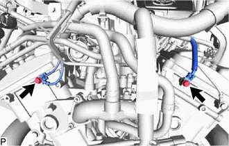
Remove the 2 bolts and wire harness from the engine.
11029
2.REMOVE V-BANK COVER BRACKET SUB-ASSEMBLY
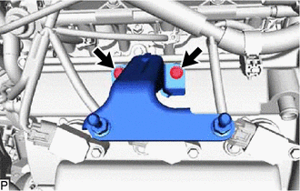
Remove the 2 bolts and V-bank cover bracket sub-assembly.
3.REMOVE WIRE HARNESS CLAMP BRACKET
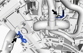
for Rear Side:
Remove the 2 bolts and 2 wire harness clamp brackets.
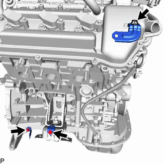
for RH Side:
Remove the 3 bolts and 3 wire harness clamp brackets.
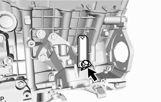
for LH Side:
Remove the bolt and wire harness clamp bracket.
4.REMOVE WATER HOSE SUB-ASSEMBLY
Slide the 2 clamps and remove the water hose sub-assembly.
12261
5.REMOVE PCV HOSE
12262
6.REMOVE NO. 2 PCV HOSE
7.REMOVE NO. 1 FUEL PIPE SUB-ASSEMBLY AND NO. 2 FUEL PIPE SUB-ASSEMBLY
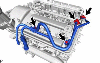
Remove the No. 2 fuel pipe clamp and disconnect the No. 1 fuel pipe sub-assembly from the fuel delivery pipe sub-assembly.
Remove the No. 2 fuel pipe clamp and disconnect the No. 2 fuel pipe sub-assembly from the fuel pressure regulator assembly.
Remove the 2 bolts, No. 1 fuel pipe sub-assembly and No. 2 fuel pipe sub-assembly.
12311
8.REMOVE FRONT NO. 1 ENGINE MOUNTING BRACKET RH
Remove the 4 bolts and front No. 1 engine mounting bracket RH.
12315
9.REMOVE FRONT NO. 1 ENGINE MOUNTING BRACKET LH
Remove the 3 bolts and front No. 1 engine mounting bracket LH.
16620
10.REMOVE V-RIBBED BELT TENSIONER ASSEMBLY
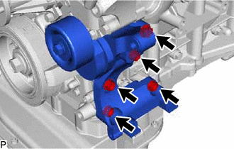
Remove the 5 bolts and V-ribbed belt tensioner assembly.
23807
11.REMOVE FUEL DELIVERY PIPE SUB-ASSEMBLY
23250
12.REMOVE FUEL INJECTOR ASSEMBLY
17111
13.REMOVE INTAKE MANIFOLD
19500
14.REMOVE IGNITION COIL ASSEMBLY
11452
15.REMOVE ENGINE OIL LEVEL DIPSTICK GUIDE
Remove the engine oil level dipstick.
Remove the bolt and pull out the engine oil level dipstick guide.
Remove the O-ring from the engine oil level dipstick guide.
16604
16.REMOVE NO. 2 IDLER PULLEY SUB-ASSEMBLY
16603
17.REMOVE NO. 1 IDLER PULLEY SUB-ASSEMBLY
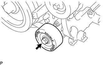
Remove the bolt and No. 1 idler pulley sub-assembly.