INTERIOR PANELS / TRIM LOWER INSTRUMENT PANEL REMOVAL
CAUTION / NOTICE / HINT
- HINT:
- ·
Use the same procedure for RHD and LHD vehicles.
·The procedure listed below is for LHD vehicles.
The necessary procedures (adjustment, calibration, initialization or registration) that must be performed after parts are removed, installed or replaced during the lower instrument panel removal/installation are shown below.
| Replacement Part or Procedure | Necessary Procedures | Effects / Inoperative when not Performed | Link |
|---|---|---|---|
| Disconnect cable from negative battery terminal | w/ Power Back Door System:
Reset back door close position |
Power door lock control system | ( ) |
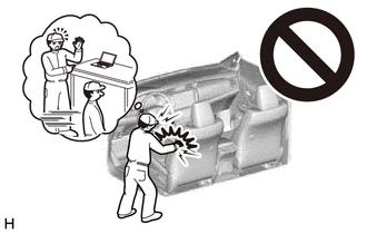
- CAUTION:
-
-
Some of these service operations affect the SRS airbag system. Read the precautionary notices concerning the SRS airbag system before servicing.
-
Click hereVehicle Interior>SUPPLEMENTAL RESTRAINT SYSTEMS>AIRBAG SYSTEM(for Type B)>PRECAUTION
PROCEDURE

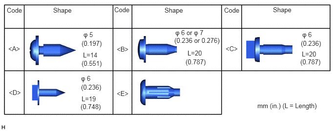
 1. TABLE OF BOLT, SCREW, NUT AND CLIP
- HINT:
-
All bolts, screws and clips relevant to installing and removing the instrument panel are shown along with their alphabetic code in the table below.
2. PRECAUTION
- NOTICE:
-
After turning the ignition switch off, waiting time may be required before disconnecting the cable from the battery terminal. Therefore, make sure to read the disconnecting the cable from the battery terminal notice before proceeding with work.
-
Click hereGeneral>INTRODUCTION>REPAIR INSTRUCTION>PRECAUTION
3.DISCONNECT CABLE FROM NEGATIVE BATTERY TERMINAL
- CAUTION:
-
Wait at least 90 seconds after disconnecting the cable from the negative (-) battery terminal to disable the SRS system.
- NOTICE:
-
When disconnecting the cable, some systems need to be initialized after the cable is reconnected.
-
Click hereGeneral>INTRODUCTION>REPAIR INSTRUCTION>INITIALIZATION
55302A
4.REMOVE UPPER INSTRUMENT PANEL SUB-ASSEMBLY
58810J
5.REMOVE CONSOLE BOX ASSEMBLY
84140
6.REMOVE HEADLIGHT DIMMER SWITCH ASSEMBLY
55522B
7.REMOVE RADIO TUNER OPENING COVER (w/o Audio)
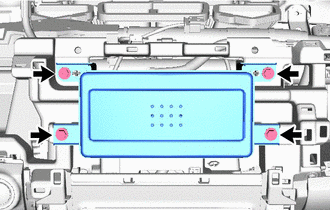
Remove the 4 screws and radio tuner opening cover.
86120
8.REMOVE RADIO RECEIVER ASSEMBLY (w/ Audio, for Radio Receiver Type)
86140A
9.REMOVE RADIO AND DISPLAY RECEIVER ASSEMBLY (w/ Audio, for Radio and Display Type)
86120L
10.REMOVE NAVIGATION RECEIVER ASSEMBLY (w/ Navigation System)
55905J
11.REMOVE CONTROL KNOB SUB-ASSEMBLY (for Manual Air Conditioning System)
84013A
12.REMOVE INTEGRATION PANEL SUB-ASSEMBLY (for Manual Air Conditioning System)
55900
13.REMOVE AIR CONDITIONING CONTROL ASSEMBLY (for Automatic Air Conditioning System)
55407C
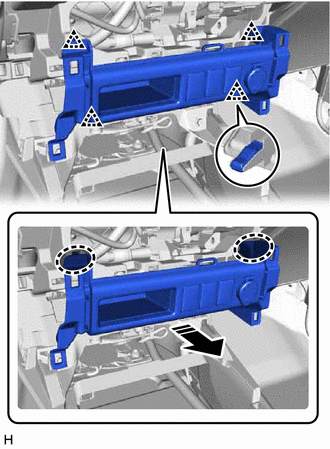
14.REMOVE LOWER INSTRUMENT COVER SUB-ASSEMBLY

|
Place Hands Here |

|
Remove in this Direction |
except 4WD:
Place your hands at the position shown in the illustration and pull as shown to detach the clip.
Disconnect the connector and remove the lower instrument cover sub-assembly.
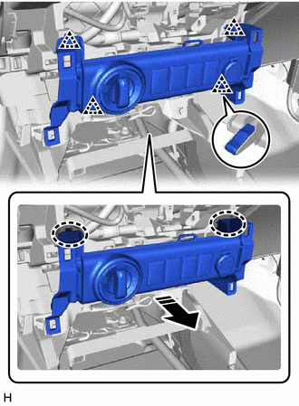
|
|
Place Hands Here |
|
|
Remove in this Direction |
for 4WD:
Place your hands at the position shown in the illustration and pull as shown to detach the clip.
Disconnect the connector and remove the lower instrument cover sub-assembly.
55447C
15.REMOVE NO. 2 SWITCH HOLE BASE
w/ Entry and Start System:
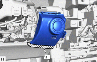
| *a | Protective Tape |
Put protective tape around the No. 2 switch hole base.
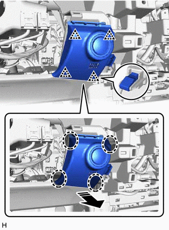
|
|
Place Hands Here |
|
|
Remove in this Direction |
Place your hands at the position shown in the illustration and pull as shown to detach the clip and remove the No. 2 switch hole base.
for Automatic Air Conditioning System:
Disconnect the cooler thermistor connector and hose.
Disconnect the connector and remove the No. 2 switch hole base.
w/o Entry and Start System:
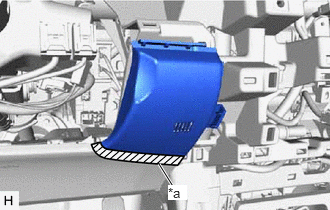
| *a | Protective Tape |
Put protective tape around the No. 2 switch hole base.
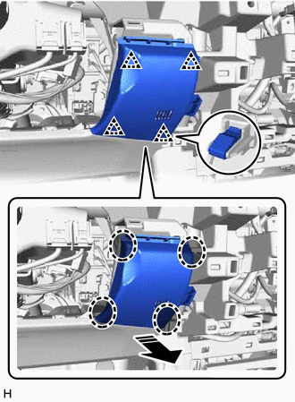
|
|
Place Hands Here |
|
|
Remove in this Direction |
Place your hands at the position shown in the illustration and pull as shown to detach the clip and remove the No. 2 switch hole base.
55606
16.REMOVE NO. 1 INSTRUMENT PANEL UNDER COVER SUB-ASSEMBLY
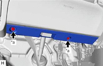
| *a | Screw <A> |
Remove the 2 screws <A>.
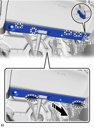
|
|
Place Hands Here |
|
|
Remove in this Direction |
Place your hands at the position shown in the illustration and pull as shown to detach the clip and guide.
Detach the claw and disconnect the DLC3 and remove the No. 1 instrument panel under cover sub-assembly.
73900
17.REMOVE LOWER NO. 1 INSTRUMENT PANEL AIRBAG ASSEMBLY
55607
18.REMOVE NO. 2 INSTRUMENT PANEL UNDER COVER SUB-ASSEMBLY
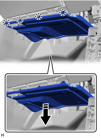
|
|
Remove in this Direction |
Detach the claw and pull as shown in the illustration.
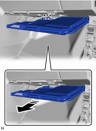
|
|
Remove in this Direction |
Pull as shown in the illustration, detach the guide and remove the No. 2 instrument panel under cover sub-assembly.
55550
19.REMOVE GLOVE COMPARTMENT DOOR ASSEMBLY
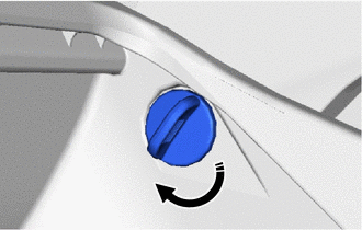
|
|
Remove in this Direction |
Twist the glove door stopper pin as shown in the illustration and remove it.
- HINT:
-
Use the same procedure for both glove door stopper pins.
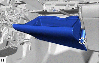
Open the glove compartment door assembly, detach the claw and disconnect the glove compartment door stopper sub-assembly.
- HINT:
-
Pull diagonally to remove the glove compartment door stopper sub-assembly.
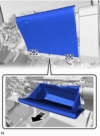
|
|
Remove in this Direction |
Pull as shown in the illustration to detach the hinge and remove the glove compartment door assembly.
55054
20.REMOVE GLOVE COMPARTMENT DOOR STOPPER SUB-ASSEMBLY
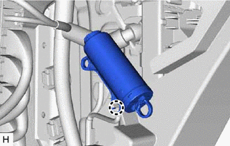
Detach the claw and remove the glove compartment door stopper sub-assembly.
55303B
21.REMOVE LOWER INSTRUMENT PANEL SUB-ASSEMBLY
Detach the clamp and disconnect the illumination light.
Remove the 7 screws <B>, 2 bolts <C> and screw <D>.
Detach the guide and disconnect the connector.
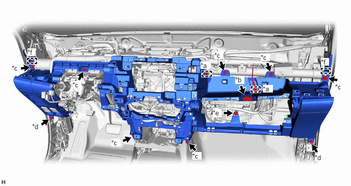
| *a | Clamp | *b | Illumination Light |
| *c | Screw <B> | *d | Bolt <C> |
| *e | Screw <D> | *f | Guide |
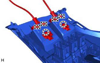
Detach the claw and guide to disconnect the hood lock control lever sub-assembly and fuel lid lock open lever.
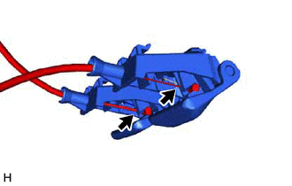
Disconnect the hood lock control cable and fuel lid lock open cable and remove the lower instrument panel sub-assembly.