1KD-FTV ENGINE MECHANICAL ENGINE UNIT INSTALLATION
CAUTION / NOTICE / HINT
- NOTICE:
- ·
When replacing the parts in the following chart (A), replace the No. 1 injection pipe sub-assembly, No. 2 injection pipe sub-assembly, No. 3 injection pipe sub-assembly, No. 4 injection pipe sub-assembly and/or fuel inlet pipe sub-assembly with new ones.
Replaced Parts (A) Pipes Requiring New Replacement ·Injector assembly (including shuffling the injector assemblies between the cylinders)
·Common rail assembly
·Cylinder head sub-assembly
·No. 1 injection pipe sub-assembly
·No. 2 injection pipe sub-assembly
·No. 3 injection pipe sub-assembly
·No. 4 injection pipe sub-assembly
·Supply pump assembly
·Common rail assembly
·Cylinder block sub-assembly
·Cylinder head sub-assembly
·Cylinder head gasket
·Timing Gear Case Assembly
Fuel inlet pipe sub-assembly
·After removing the No. 1 injection pipe sub-assembly, No. 2 injection pipe sub-assembly, No. 3 injection pipe sub-assembly, No. 4 injection pipe sub-assembly and fuel inlet pipe sub-assembly, clean them with a brush and compressed air.
PROCEDURE

 12315
1.INSTALL FRONT NO. 1 ENGINE MOUNTING BRACKET LH
Install the front No. 1 engine mounting bracket LH to the cylinder block sub-assembly with the 4 bolts.
- Torque:
- 68 N*m (693 kgf*cm, 50 ft.*lbf)
12311
2.INSTALL FRONT NO. 1 ENGINE MOUNTING BRACKET RH
Install the front No. 1 engine mounting bracket RH to the cylinder block sub-assembly with the 4 bolts.
- Torque:
- 68 N*m (693 kgf*cm, 50 ft.*lbf)
3.INSTALL ENGINE COOLANT TEMPERATURE SENSOR
4.INSTALL CAMSHAFT POSITION SENSOR
5.INSTALL CRANKSHAFT POSITION SENSOR
44320
6.INSTALL VANE PUMP ASSEMBLY
Install a new O-ring to the vane pump assembly.
Install the vane pump assembly to the timing gear case assembly with the 2 nuts.
- Torque:
- 39 N*m (398 kgf*cm, 29 ft.*lbf)
29300
7.INSTALL VACUUM PUMP ASSEMBLY
Install 2 new O-rings to the vacuum pump assembly.
Install the vacuum pump assembly to the timing gear cover with the 2 nuts.
- Torque:
- 20.6 N*m (210 kgf*cm, 15 ft.*lbf)
15701C
8.INSTALL OIL COOLER COVER SUB-ASSEMBLY
19850
9.INSTALL GLOW PLUG ASSEMBLY
25617A
10.INSTALL NO. 2 EGR HOLE COVER PLATE
Install a new gasket and the No. 2 EGR hole cover plate with the 2 nuts.
- Torque:
- 13 N*m (133 kgf*cm, 10 ft.*lbf)
17111
11.INSTALL INTAKE MANIFOLD
22100
12.INSTALL FUEL SUPPLY PUMP ASSEMBLY
23810A
13.INSTALL COMMON RAIL ASSEMBLY
23804C
14.INSTALL FUEL INLET PIPE SUB-ASSEMBLY
15301
15.INSTALL ENGINE OIL LEVEL DIPSTICK GUIDE
23770
16.INSTALL NO. 2 NOZZLE LEAKAGE PIPE ASSEMBLY
23704
17.INSTALL NO. 4 INJECTION PIPE SUB-ASSEMBLY
23701
18.INSTALL NO. 1, NO. 2 AND NO. 3 INJECTION PIPE SUB-ASSEMBLY
15601
19.INSTALL OIL FILTER SUB-ASSEMBLY
17861
20.INSTALL INTAKE AIR CONNECTOR
17873A
21.INSTALL NO. 2 INTAKE AIR CONNECTOR BRACKET
17118
22.INSTALL MANIFOLD STAY
26100G
23.INSTALL DIESEL THROTTLE BODY ASSEMBLY
25861C
24.INSTALL VACUUM SWITCHING VALVE BRACKET
16331
25.INSTALL WATER OUTLET
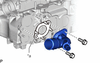
| *a | Claw |
Install a new gasket and the water outlet to the cylinder head sub-assembly with the 2 bolts.
- Torque:
- 19 N*m (194 kgf*cm, 14 ft.*lbf)
- HINT:
-
Make sure the claws of the gasket face the water outlet.
16331A
26.INSTALL THERMOSTAT
16321
27.INSTALL WATER INLET
88431
28.INSTALL NO. 1 COMPRESSOR MOUNTING BRACKET
Install the No. 1 compressor mounting bracket to the cylinder block sub-assembly with the 4 bolts.
- Torque:
- 45 N*m (459 kgf*cm, 33 ft.*lbf)
16620
29.INSTALL V-RIBBED BELT TENSIONER ASSEMBLY
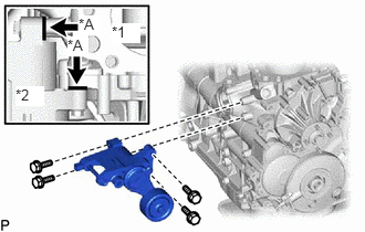
| *1 | Cylinder Block Sub-assembly |
| *2 | V-ribbed Belt Tensioner |
Install the V-ribbed belt tensioner assembly to the cylinder block sub-assembly with the 4 bolts.
- Torque:
- 21 N*m (214 kgf*cm, 15 ft.*lbf)
- HINT:
-
Firmly press and hold the V-ribbed belt tensioner assembly against the cylinder block sub-assembly to eliminate any gaps in the areas labeled A in the illustration. Then uniformly tighten the 4 bolts.
12511C
30.INSTALL GENERATOR BRACKET
Install the generator bracket with the bolt.
- Torque:
- 25 N*m (255 kgf*cm, 18 ft.*lbf)
27020
31.INSTALL GENERATOR ASSEMBLY
88440D
32.INSTALL NO. 2 IDLE PULLEY ASSEMBLY
33.INSTALL EXHAUST MANIFOLD WITH TURBOCHARGER
Install a new gasket and the exhaust manifold with turbocharger to the cylinder head sub-assembly with the 8 spacers, 8 collars and 8 new nuts.
- Torque:
- 40 N*m (408 kgf*cm, 30 ft.*lbf)
17291
34.INSTALL TURBINE OUTLET ELBOW
16284
35.CONNECT NO. 1 TURBO WATER HOSE
17167
36.INSTALL NO. 1 EXHAUST MANIFOLD HEAT INSULATOR
17271
37.INSTALL NO. 1 TURBO INSULATOR
12229
38.INSTALL VENTILATION PIPE
17945
39.INSTALL INTERCOOLER SUPPORT BRACKET
Install the intercooler support bracket to the cylinder head sub-assembly with the 2 bolts.
- Torque:
- 32 N*m (326 kgf*cm, 24 ft.*lbf)
17946
40.INSTALL NO. 2 INTERCOOLER SUPPORT BRACKET
Install the No. 2 intercooler support bracket to the cylinder head sub-assembly with the 2 bolts.
- Torque:
- 32 N*m (326 kgf*cm, 24 ft.*lbf)
13408
41.INSTALL CRANKSHAFT PULLEY SUB-ASSEMBLY
13505
42.INSTALL NO. 1 TIMING BELT IDLER SUB-ASSEMBLY
13568
43.INSTALL TIMING BELT
11322A
44.INSTALL NO. 1 TIMING BELT COVER